background image

4

2.1

Controls

The BA526C is controlled and calibrated via four
front panel push-button switches.

In the display

mode i.e. when the instrument is displaying a
4/20mA input current, these switches have the
following functions:

P

While this button is pushed the digital
display will show the input current in
mA, or as a percentage of the
instrument span depending upon how
the instrument has been programmed.
When the button is released the normal
display in engineering units will return.
The function of this push-button is
modified when either alarm is enabled.

Down

While this button is pushed the digital
display will show the calibration with a
4mA input. When released the normal
display in engineering units will return.

Up

While this button is pushed the digital
display will show the calibration with a
20mA input.

When released the

normal displays in engineering units will
return.

E

No function in the display mode.

3.

APPLICATIONS

3.1

Transmitter loops

A BA526C indicator may be connected in series
with almost any 4/20mA current loop that can
tolerate the 1.1V drop required to operate the

instrument (increases to 1.2V at -20ºC), and be
calibrated to display the measured variable or
control signal in engineering units.

Fig 2 illustrates a typical application in which a
BA526C indicator is connected in series with a
2-wire transmitter.

Fig 2  BA526C in a transmitter loop

Considering the example shown in Fig 2, the sum
of the maximum voltage drops of all the
components in the loop must be less than the
minimum power supply voltage.

Therefore at 20mA the power supply in this
example must have an output greater than 16.6V

Minimum operating voltage of 2-wire Tx

10.0

Maximum voltage drop caused by controller

5.0

Maximum voltage drop caused by BA526C

1.2

Maximum voltage drop caused by cables

0.4

                                                                       ______

16.6V

Summary of Contents for BA526C

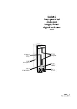
Page 1: ...Issue 9 1st June 2017 Alarm setpoints Digital display Label information Alarm annunciators Push buttons Analogue display BA526C loop powered analogue bargraph and digital indicator issue 9 ...

Page 2: ...Examples 6 1 Using an external current source 6 2 Using the internal references 7 Maintenance 7 1 Fault finding during commissioning 7 2 Fault finding after commissioning 7 3 Servicing 7 4 Routine maintenance 7 5 Guarantee 7 6 Customer comments 8 Accessories 8 1 Units of measurement and instrument identification 8 2 Alarms 8 2 1 Solid state output 8 2 2 Programming and adjustment 8 2 3 Alarm enabl...

Page 3: ...e bargraph and digital display may be offset to indicate deviation from a specified input current The indicator is housed in a robust 144 x 48 panel mounting DIN enclosure with an IP65 sealed front 2 OPERATION Fig 1 shows a simplified block diagram of a BA526C The 4 20mA input current flows through resistor R1 and forward biased diode D1 The voltage developed across D1 which is relatively constant...

Page 4: ...20mA input When released the normal displays in engineering units will return E No function in the display mode 3 APPLICATIONS 3 1 Transmitter loops A BA526C indicator may be connected in series with almost any 4 20mA current loop that can tolerate the 1 1V drop required to operate the instrument increases to 1 2V at 20ºC and be calibrated to display the measured variable or control signal in engi...

Page 5: ...5 protection and a gasket seals the joint between the instrument enclosure and the panel The instrument may be installed in any panel providing the environmental limits shown in the specification are not exceeded Fig 4 shows the overall dimensions of the BA526C and panel cut out To achieve an IP65 seal between the instrument enclosure and the panel the smaller cut out must be used and the instrume...

Page 6: ... menu which is shown diagramatically in Fig 6 Each function is summarised in section 5 1 which includes references to more detailed information Although this simple menu driven system enables most adjustments to be made without repeated reference to this manual it is recommend that at least the summary of the programmable functions in section 5 1 is read before attempting programming or recalibrat...

Page 7: ... the 4 digit display so that larger number may be displayed See section 5 5 d P Decimal point Positions a dummy decimal point between any of the digits or turns it off See section 5 6 Display Description of function bAr Bargraph display Selects a column or single segment display and defines whether the input current is displayed on the left hand or on both 100 segment bargraphs See section 5 7 CAL...

Page 8: ...ifferential flowmeters which have a square law output The root extractor linearises the input current between 4 04mA and 20mA 5 to 100 flow so that the flow signal is displayed in linear units For inputs below 4 04mA the BA526C displays zero To activate the square root extractor select root from the menu and press P which will reveal if the function is On or OFF If the function is set as required ...

Page 9: ...he instrument to the main programme menu 5 8 Calibration using an external current source CAL This function enables the zero and span of the digital display to be adjusted using an external calibrated current source When used with an accurate traceable current source this is the preferred method of calibration The analogue bargraph is automatically calibrated when the digital display is calibrated...

Page 10: ... be calibrated To gain access to the sub menu select Cond from the main menu and press P The indicator will display 0000 Using the Up and Down buttons and the P button to move to the next digit enter the password SurE Note that S is entered as 5 Pressing E will then give access to the two functions in the sub menu 5 10 1 AC rejection FrE CAUTION If the mains filter frequency is changed the indicat...

Page 11: ...11 ...

Page 12: ...put current as a percentage of the span The analogue display continues to operate normally while the P button is operated To check or change the parameter select C P from the main menu and press P to reveal the current setting Pressing the Up or Down button will toggle the setting between 4 20 the current display and PC the percentage display When set as required press E to return to the main menu...

Page 13: ...unction has been used Fig 8 Effect of nulling at two different inputs 5 13 Security code COdE The calibration and conditioning of the instrument may be protected by a four digit security code which must be entered before access to the programme menu is granted New instruments are programmed with the default security code 0000 which allows unrestricted access to all programming functions To enter a...

Page 14: ...nd the existing security code is 1209 In the operating mode the indicator is required to display the input current as a percentage of span when the P push button is operated Step 1 Connect indicator to calibrator Connect the indicator to an accurate external current source Terminal 1 positive The indicator will automatically perform the initialisation routine described in section 2 and then displa...

Page 15: ... will request a 20mA input by displaying SPAn Set the input current to 20 0000 0 0004mA and again press P which will reveal the existing display at 20mA Using the Up Down and P push buttons enter the required display of 1500 0 Press E twice to return to the main menu The indicator will display Ent while storing this figure The analogue bargraph will be automatically calibrated to display 0 with 4m...

Page 16: ... 1500 0 Press E to return to the SPAn prompt Press E again to return to the main menu The analogue bargraph will be automatically calibrated to display 0 with 4mA input and full scale with 20mA input Step 7 Return to display mode Following completion of calibration return to the display mode by pressing E 7 MAINTENANCE 7 1 Fault finding during commissioning If a BA526C fails to function during com...

Page 17: ...Customer comments BEKA associates is always pleased to receive comments from customers about our products and services All communications are acknowledged and whenever possible suggestions are implemented 8 ACCESSORIES 8 1 Units of measurement and instrument identification All BA526C indicators are fitted with a display label behind the armoured glass window This label can be supplied with any ana...

Page 18: ...ght hand analogue bargraph indicates the position of the alarm setpoint s so they can be easily compared with the measured value The type of setpoint display depends upon alarm conditioning and the relative values of the two setpoints When alarm 1 is programmed as a low alarm and alarm 2 as a high alarm the display shown in Fig 11A will be produced providing setpoint 1 is less than setpoint 2 If t...

Page 19: ...d 10 should be connected to the positive side of the supply Ron 5ohms 0 6V Roff greater than 180k Note Because of the series protection diode some test meters may not detect a closed alarm output Fig 12 Equivalent circuit of each alarm output Fig 13 Typical alarm application Fig 13 shows a typical application for the BA526C indicator with alarms A solenoid valve is controlled by one alarm output w...

Page 20: ...E P Cond ALr1 E E 0000 AcCd C P E E Alarms Main menu Main menu Access Enable or to toggle between On and OFF Security Code For Direct Access to Setpoints Enter code by pressing and to move to next digit Code 0000 allows direct access P Access to setpoints from display mode OFF EnbL P E Alarm Enable or to toggle between On and OFF E SP1 00 00 P E E Setpoint Enter by pressing and to move to next dig...

Page 21: ...button to move to the next digit When the required setpoint has been entered press E to return to the alarm menu 8 2 5 Alarm function HI LO Each alarm can be conditioned as a high or low alarm To check or change the alarm function select HI LO from the alarm menu and press P to reveal the current setting The function can be changed by pressing the Up or Down buttons followed by the E button to ret...

Page 22: ...rgraph display When the function is enabled and an alarm occurs the setpoint bar or column flashes To check or change the display alarm identification status select FLASH from the alarm menu and press P to reveal the current setting The function can be changed by pressing the Up or Down button followed by the E button to return to the alarm menu 8 2 11 Access Setpoint AcSP This function controls a...

Page 23: ...or may be returned to the display mode by pressing E again Direct access to the alarm setpoints is only available when the menu is enabled see section 8 2 11 8 3 Lineariser The indicator can be supplied with a sixteen point lineariser which may be adjusted to compensate for almost any non linear variable For example a level signal from a horizontal cylindrical tank may be linearised by the indicat...

Page 24: ...ter input current at which each break point and to move to next digit P Enter requied display at each break point by pressing or and and to move to next digit P Calibration using internal references Without the need for accurate input current Enter the number of break points followed by the position and the required display E bAr Add 3 16 P E P E CAL 3 16 dEL P E 0 16 0000 P E PtS P E E E 1000 1 1...

Page 25: ... can be selected using the Up and Down push buttons The delete break point function dEL operates in a similar manner to the Add function described above When the required number of break points has been entered return to the sub menu by pressing E The indicator will display Add or dEL depending upon the last function used Each break point can now be programmed Select PtS from the sub menu and pres...

Page 26: ...tor will display Add or dEL depending upon the last function used The required indicator display at each break point can now be entered followed by the input current at which each break point occurs To enter the required display at any break point select dISP from the sub menu and press P which will select the first break point 0 n where n is the total number of break points selected The selected ...

Page 27: ...stalled in poorly illuminated areas The backlight is electrically isolated from the measuring circuit and may be powered from any 18 to 30V dc supply The backlight brilliance may be reduced by reducing the supply voltage below 18V or by fitting a current limiting resistor in series with the supply Fig 18 Backlight power supply ...

Reviews: