


2
1.
Description
2.
Operation
2.1 Controls
3.
Applications
3.1 Transmitter loops
3.2 Remote indication
4.
Installation
4.1 Location
4.2 Installation procedure
4.3 EMC
5.
Programming and Calibration
5.1 Summary of programmable
functions
5.2 Root extractor
5.3 Digital display
5.4 Digital resolution
5.5 Dummy trailing zero
5.6 Position of decimal point
5.7 Bargraph display
5.8 Calibration using an external
current
source.
5.9 Calibration using internal
references
5.10 Conditioning sub-menu
5.10.1 AC rejection
5.10.2 Calibration of internal
references.
5.11 Function of the
P
push-button
5.12 Null display function
5.13 Security code
5.14 Over and under-range
6.
Calibration Examples
6.1 Using an external current source
6.2 Using the internal references
7.
Maintenance
7.1 Fault finding during commissioning
7.2 Fault finding after commissioning
7.3 Servicing
7.4 Routine maintenance
7.5 Guarantee
7.6 Customer comments
8.
Accessories
8.1 Units of measurement and
instrument identification.
8.2 Alarms
8.2.1 Solid state output
8.2.2 Programming and
adjustment
8.2.3 Alarm enable
8.2.4 Setpoint adjustment
8.2.5 Alarm function
8.2.6 Alarm output status
8.2.7 Hysteresis
8.2.8 Alarm delay
8.2.9 Alarm silence time
8.2.10 Display alarm identification
8.2.11 Access setpoint
8.2.12 Adjusting alarm setpoints
from display mode.
8.3 Lineariser
8.3.1 Calibration using an
external
current source.
8.3.2 Calibration using internal
references.
8.4 Display backlight
CONTENTS
The BA326C is CE marked to show compliance with the European EMC Directive 2014/30/EU
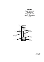
Summary of Contents for BA526C
Page 11: ...11 ...


