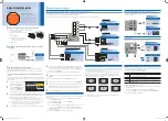
Fig 3 Dimensions and terminal connections
5. MAINTENANCE
5.1 Fault finding during commissioning
If
a
BA414DF-F
fails
to
function
during
commissioning the following procedure should be
followed:
Symptom
Cause
Check:
No Display
Instrument not
correctly
connected or
powered.
Between
terminals 1 & 2:
FISCO 9 & 17.5V
Ex ia 9 to 22V
Ex ic 9 & 32V
Display shows
‘9.9.9.9.9’ with all
decimal points
flashing; all
bargraph
segments
activated and
bargraph scale
flashing.
Value
over-range
Variable source
Decimal point
configuration.
Display shows
‘-9.9.9.9.9’ with
all decimal points
flashing; no
bargraph
segments
activated and
bargraph scale
flashing.
Value
under-range
Variable source
Decimal point
configuration
Display
alternates
between value
and the word
‘bAd’. Bargraph
flashes.
Status of fieldbus
variable has a
quality of ‘BAD’
or a fault state is
active.
Display has not
yet received
data.
Variable source
Fieldbus
configuration.
Bargraph scale
flashes.
Variable is
outside the limits
defined for the
bargraph.
Bargraph
configuration.
All display
segments
activated.
Display is
initialising.
This is normal
operation, after a
few seconds the
firmware version
will be displayed
prior to entering
the operational
mode.
5.2 Fault finding after commissioning
ENSURE PLANT SAFETY BEFORE
STARTING MAINTENANCE
Live
maintenance
is
permitted
on
intrinsically safe equipment installed in a
hazardous area, but only certified test
equipment should be used unless a gas
clearance certificate is available.
If a BA414DF-F fails after it has been functioning
correctly, the table shown in section 5.1 may help
to identify the cause of the failure.
If this procedure does not reveal the cause of the
fault, it is recommended that the instrument is
replaced.
7


