


10.3.2 Ex nA certification
Each alarm output is a separate galvanically isolated
Ex nA circuit with the following input parameters:
Ui
=
30V dc
Ii
=
200mA
This allows each alarm output to switch any dc circuit
providing that in normal operation the maximum
supply voltage is not greater than 30V dc and the
switched current is not greater than 200mA.
Providing that the BA364NG Counter is correctly
installed in Zone 2 the two alarm outputs may be used
to switch suitably protected equipment located in
Zone 1 or 2 of a hazardous area, or equipment
located in a safe area.
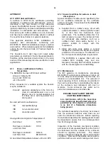
Fig 14 shows an application in which a BA364NG
Counter mounted in Zone 2 is displaying the output
from a Flameproof switch contact located in Zone 1.
Alarm 1 is switching an Ex e sounder in Zone 1 and
alarm 2 is switching a sounder located in the safe
area.
Fig 14 Typical alarm application
To comply with the requirements of EN 60079-14
Electrical installations design, selection and erection
,
each of the wires entering the hazardous area should
be individually fused and contain a means of isolation.
These two requirements are frequently satisfied by
using fuse holders with easily removable fuses and
removing the fuses to achieve isolation. This is a
satisfactory method at the low voltages and currents
common in instrumentation systems. Clear
identification of, and easy access to the means of
isolation is essential for their effective use. It is also
necessary to ensure that the maintenance procedure
makes sure that unauthorised re-closure of the
switches does not occur. It is not considered
necessary to have a means of isolation or electrical
protection for the screen. Fig 2 illustrates an
example of this type of fused terminal block.
For some applications Ex nA instrumentation
energised by a current limited power supply or
instrument that can be switched off, is often
considered adequate and to comply with the
requirements of the standard.
10.3.3 Summary of configuration functions
When a BA364NG Counter is supplied with alarms
the Counter configuration menu is extended as
shown in Fig 15. Each alarm may be configured
to operate on the rate or total display.
For simplicity Fig 15 only shows the configurable
functions on the rate option of alarm AL1, the total
option is identical except that the total alarms can
not have hysteresis. Configuration of alarm AL2
is identical to alarm AL1.
The following table summarises each of the alarm
configuration functions and includes a cross
reference to more detailed information. Again only
the functions on alarm AL1 are listed.
Display Summary of function
EnbL
Alarm enable
Enables or disables the alarm without
changing the alarm parameters.
See section 10.3.4
tYPE
Type of alarm
Defines whether the alarm operates on
the rate or total display.
See section 10.3.5
5P1r
Alarm setpoint 1
or
Adjusts the alarm setpoint. The
5P1t
alarm is activated when the rate or
total display equals the setpoint.
Note:
5P1r
is displayed for a rate alarm
and
5P1t
for a total alarm.
See section 10.3.6
HI.
LO
Alarm function
Defines whether the alarm has a high
or low function.
See section 10.3.7
no
.
nc
Normally open or normally closed
output.
Determines whether the single pole
alarm output is open or closed in the
non-alarm condition.
See section 10.3.8
36
Summary of Contents for BA364NG
Page 1: ...Issue 6 9th July 2019 BA364NG Two Input Ex nA and Ex tc Counter Issue 6 ...
Page 4: ...4 ...
Page 18: ...18 ...
Page 19: ...19 ...


