


4
2.1
Controls
Both models are controlled and calibrated via four
front panel push buttons.
In the display mode i.e.
when the indicator is displaying a process variable,
these push buttons have the following functions:
(
While this button is pushed the
indicator will display the input current
in mA, or as a percentage of the
instrument span depending upon how
the indicator has been configured.
When the button is released the
normal display in engineering units
will return. The function of this push
button is modified when optional
alarms are fitted to the indicator.
&
While this button is pushed the
indicator will display the numerical
value and analogue bargraph* the
indicator has been calibrated to
display with a 4mA
Φ
input.
When
released
the
normal
display
in
engineering units will return.
*
While this button is pushed the
indicator will display the numerical
value and analogue bargraph* the
indicator has been calibrated to
display with a 20mA
Φ
input.
When
released
the
normal
display
in
engineering units will return.
)
No function in the display mode
unless the tare function is being used.
(
+
&
Indicator displays firmware number
followed by version.
(
+
*
Provides direct access to the alarm
setpoints when the indicator is fitted
with optional alarms and the
AC5P
access setpoints function has been
enabled.
(
+
)
Provides access to the configuration
menu via optional security code.
Note:
* BA524G-SS-PM
only
Φ
If
the
indicator
has
been
calibrated
using
the
CAL
function, calibration
points
may
not be 4 and 20mA.
3.
APPLICATIONS
3.1
Transmitter loops
Both models may be connected in series with
almost any 4/20mA current loop and calibrated to
display the measured variable or control signal in
engineering units.
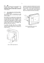
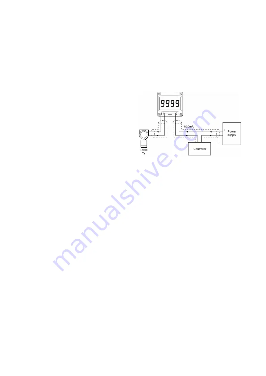
Fig 2 illustrates a typical application in which an
indicator is connected in series with a 2-wire
transmitter.
Fig 2 Indicator in transmitter loop
Considering the example shown in Fig 2, the sum
of the maximum voltage drops of all the
components in the loop must be less than the
minimum power supply voltage.
Minimum operating voltage of 2-wire Tx
10.0
Maximum voltage drop caused by controller 5.0
Maximum voltage drop caused by indicator 1.3
Maximum voltage caused by cables
0.4
_____
16.7V
Therefore in this example at 20mA the power
supply must have a minimum output of 16.7V
3.2
Remote indication
All models may be driven from any 4/20mA signal
to provide a remote indication.
Fig 3 shows a
typical application in which the 4/20mA output from
a gas analyser is connected to a BA504G-SS-PM
loop powered indicator to provide a remote
indication of the analyser’s output.
Again it is
necessary to ensure that the voltage capability of
the 4/20mA source is greater than the sum of the
voltage drops introduced by the indicator and the
cable resistance.


