User Guide Revision 1.12
11
3.
Mechanical Installation
3.1.
General
The drive should be mounted in a vertical position only on a flat, flame resistant vibration free mounting using the integral holes.
The drive must be installed in a pollution degree 1 or 2 environment only.
Do not mount flammable material close to the drive
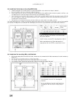
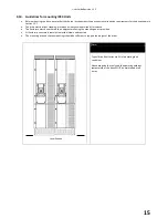
Ensure that the minimum cooling air gaps, as detailed in section 3.8 thru 3.10 are left clear
Ensure that the ambient temperature range does not exceed the permissible limits for the drive given in section 13.1
Provide suitable clean, moisture and contaminant free cooling air sufficient to fulfil the cooling requirements of the drive according
to section 13.1
3.2.
Before Installation
Carefully Unpack the drive and check for any signs of damage. Notify the shipper immediately if any exist.
Check the drive rating label to ensure it is of the correct type and power requirements for the application.
Store the drive in its box until required. Storage should be clean and dry and within the temperature range –40°C to +60°C
3.3.
UL Compliant Installation
Note the following for UL-compliant installation:
The drive can be operated within an ambient temperature range as stated in section 13.1
For IP20 units, installation is required in a pollution degree 1 environment
For IP55 AND IP66 units, installation in a pollution degree 2 environment is permissible
UL Listed ring terminals / lugs must be used for all bus bar and grounding connections
3.4.
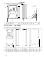
Mechanical dimensions and Mounting – IP20 Units
Drive
Size
A
B
C
D
E
F
G
H
I
J
mm
in
mm
in
mm
in
mm
in
mm
in
mm
in
mm
in
mm
in
mm
in
mm
2
221
8.70
207
8.15
137
5.39
209
8.23
5.3
0.21
2
221
8.70
207
8.15
137
5.39
209
8.23
5.3
3
261
10.28
246
9.69
-
-
247
9.72
6
0.24
3
261
10.28
246
9.69
-
-
247
9.72
6
Control Terminal Torque Settings :
All Sizes : 0.8 Nm (7 lb-in)
Power Terminal Torque Settings :
All Sizes : 1 Nm (8.85 lb-in)
IP20 Units are intended for installation within a control cabinet.
When mounting with screws
o
Using the drive as a template, or the dimensions shown above, mark the locations for drilling
o
Ensure that when mounting locations are drilled, the dust from drilling does not enter the drive
o
Mount the drive to the cabinet back-plate using suitable M5 mounting screws
o
Position the drive, and tighten the mounting screws securely
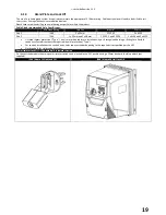
When Din Rail Mounting (Frame Size 2 Only)
o
Locate the DIN rail mounting slot on the rear of the drive onto the top of the DIN rail first
o
Press the bottom of the drive onto the DIN rail until the lower clip attaches to the DIN rail
o
If necessary, use a suitable flat blade screw driver to pull the DIN rail clip down to allow the drive to mount securely on the
rail
o
To remove the drive from the DIN rail, use a suitable flat blade screwdriver to pull the release tab downwards, and lift the
bottom of the drive away from the rail first
Summary of Contents for HVAC H2
Page 1: ......
Page 72: ...User Guide Revision 1 12 72 82 H2MAN BE_V1 11...


