8. Push die out onto die cart.
9. Reverse procedure to install die.
INSTRUCTIONS FOR SHARPENING TEETH
Remove the entire die from the press as a unit and sepa-
rate it into a top and bottom die set. Keep all teeth
attached to the die plates, however, the die shoes may be
removed from the die plates for ease in grinding teeth.
The stripper plates and urethane stripper plugs must be
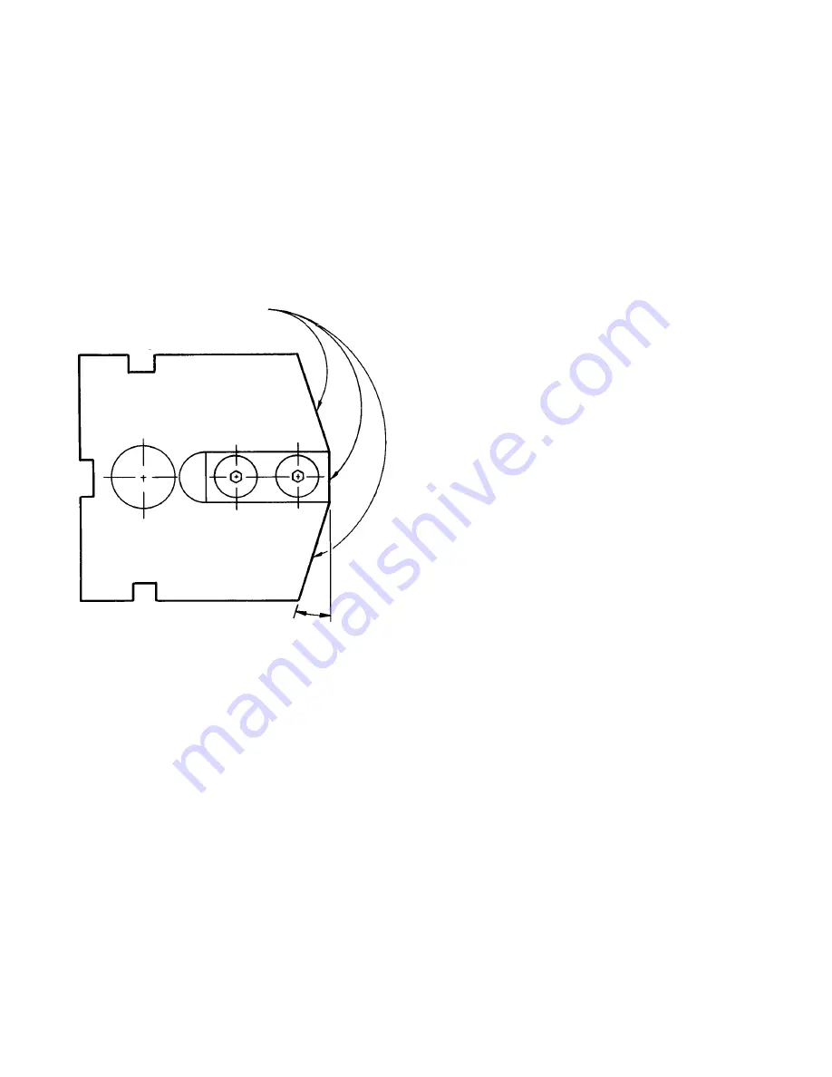
removed before the teeth are ground. Grind teeth of the
top and bottom as a unit. Teeth shall be ground on tops
and both adjoining angled sides. The sides are ground
at an angle of 9° or 18°, depending on machine model.
This angle is not critical, however, both sides should be
the same. The die may now be reassembled and placed
back into the machine. The die and press each have a
marking labeled “Front”. The die is symmetrical, but it
should be placed back in the press as originally assem-
bled. If grinding equipment is not available to sharpen
teeth as a unit, they may be ground individually. Read
the instructions for the procedure to remove and replace
teeth.
PROCEDURE FOR REPLACING TEETH
OR OTHER PARTS OF THE DIE
Remove the die from the press as a unit and separate it
into the top and bottom die sets. Next, remove the strip-
per plates and and urethane stripper plugs, tooth clamps
and rod. Teeth that need replacing may now be lifted off
the die plate. In replacing new teeth, it is very important
that all parts be cleaned thoroughly, making certain that
no lint from wiping rags or other foreign material gets
between the teeth. A spare tooth should be used for indi-
vidually checking clearance between all teeth. This clear-
ance should be .002” (0.05mm) minimum to .007”
(0.18mm) maximum around all parts of mating teeth.
After the clearance is determined to be correct, the teeth
in the bottom die set should be securely fastened by
means of the clamps and rod. The nuts on the rod
should be tightened with a torque wrench to 120 foot
pounds (163 N-M).
The two sets of set screws in each end keeper should
also be tightened at this time. These are locked in
placed with a second set of socket head set screws. The
teeth in the top die set should be tightened securely with
the rod, but only tight enough with the clamps to hold
them in place so they are allowed to move for adjustment
after the top and bottom die sections have been slipped
together. The top and bottom die sections should be
slipped together without the urethane stripper plugs and
stripper plates. At this time, clearance between top and
bottom mating teeth should be checked and adjusted if
necessary. This adjustment can be accomplished by
means of the set screws in the keepers on both ends of
the top die section. After it is determined that the die
meshes properly, the clamps of the top die should be
tightened and the urethane stripper plugs and stripper
plates replaced in the die. The entire die may now be
returned to the press.
PROCEDURE FOR REPLACING CYLINDER SEAL
1. Remove the urethane roller (615059) from one side of
the press.
2. Remove the top and bottom bolts holding the com-
plete die in place, and remove the complete die unit
from the press.
3. Remove the screws that secure the ram plate to the
pistons and then remove both ram plate skirts
(616113) and the ram plate (616112).
4. Bolt a long bar or pipe to the piston (616002) - there is
one threaded hole in the top of each piston. Remove the
piston upward from the cylinder (616099).
5. Replace the defective seal (3308009) in the cylinder,
with the lips of the seal pointing downwards.
Lubricate the seal for easier assembly.
6. Also, check the “O”ring #331 (2748014), under the
cylinder, for leakage and replace as required.
7. Reverse steps 1, 2, 3 and 4 to assemble. When
replacing pistons, apply pressure downwards as
evenly as possible so that lips of the seals will not be
cut or damaged.
HOLE PUNCH FOR SPLICE DETECTION
For strip joining dies equipped with a hole punch assem-
bly, 1½” or 2” (38mm or 51mm) diameter on the exit side
of the die, you can sharpen the round punch portion and
the die plate one or more times until a total of 0.075” to
0.100” (1.9mm to 2.5mm) maximum has been removed,
depending upon the thickness of the material being
joined. The following spare parts can be ordered by
complete description and you must indicate the diameter
of the hole punch, press model number and serial num-
ber.
1. Spare hole punch and die plate. (You will need to
locate and drill dowel pin holes to properly match up
the new mating punch and die plate.)
2. Urethane stripper ring (616270) over the hole punch
for splice detection assembly.
Original Length 2.500” (63.5mm)
Sharpen these three surfaces.
Do not grind off more than .060” (1.5mm)
total during successive sharpenings.
F-13569-5
Rev. 7-5-05 5-15-80
2
9° or 18° depending on machine model.


