Access from the user program
KL3311, KL3312, KL3314 and KL3302
39
Version: 4.2
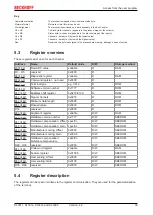
Key
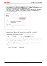
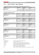
Complete evaluation
The terminal is mapped with control and status byte.
Motorola format
Motorola or Intel format can be set.
Word alignment
The terminal is positioned on a word boundary in the Bus Coupler.
Ch n CB
Control byte for channel n (appears in the process image of the outputs).
Ch n SB
Status byte for channel n (appears in the process image of the inputs).
Ch n D0
Channel n, data byte 0 (byte with the lowest value)
Ch n D1
Channel n, data byte 1 (byte with the highest value)
Res.
Reserved: this byte is assigned to the process data memory, although it has no function.
5.3
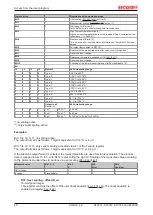
Register overview
These registers exist once for each channel
Address
Name
Default value
R/W
Storage medium
Raw ADC value
variable
R
RAM
R1…R5
reserved
0x0000
R
Diagnostic register
variable
R
RAM
Command register - not used
0x0000
R
Terminal type
e.g. 3312
R
ROM
Software version number
0x????
R
ROM
Multiplex shift register
0x0218/0130
R
ROM
Signal channels
0x0218
R
ROM
Minimum data length
0x0098
R
ROM
Data structure
0x0000
R
ROM
R14
reserved
0x0000
R
Alignment register
variable
R/W
RAM
Hardware version number
0x????
R/W
SEEROM
Hardware compensation: Offset specific
R/W
SEEROM
Hardware compensation: Gain
specific
R/W
SEEROM
Manufacturer scaling: Offset
0x0000
R/W
SEEROM
Manufacturer scaling: Gain
0x00A0
R/W
SEEROM
Hardware compensation:
Reference temperature
specific
R/W
SEEROM
R22…R30
reserved
0x0000
R/W
SEEROM
Code word register
variable
R/W
RAM
Feature register
0x01006
R/W
SEEROM
User scaling: Offset
0x0000
R/W
SEEROM
User scaling: Gain
0x0100
R/W
SEEROM
R35…R63
reserved
0x0000
R/W
SEEROM
5.4
Register description
The registers can be read or written via the register communication. They are used for the parameterization
of the terminal.

