


Operation
EP1918
42
Version: 1.1.0
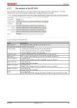
4.5.6
Cycle time of the safety project
The execution time of the TwinSAFE logic can be read from the CoE objects listed below. To determine the
cycle time, it has to be multiplied with 1.25, because this is the factor used internally for generating a delay
time before the next cycle.
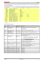
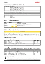
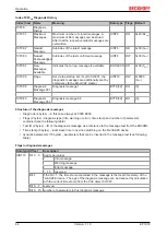
Index FEA0
hex
: CTRL Diag Data
Index
Name
Meaning
Flags Default
FEA0:09 Actual Safety Control
Task Execution Time
Current execution time of the TwinSAFE logic with a
logic state of 1 (RUN)
Cycle time = 1.25 * value
(average value of 64 cycles)
RO
0
hex
FEA0:0A Min Safety Control
Task Execution Time
Minimum execution time of the TwinSAFE logic with a
logic state of 1 (RUN)
Cycle time = 1.25 * value
RO
0
hex
FEA0:0B Max Safety Control
Task Execution Time
Maximum execution time of the TwinSAFE logic with a
logic state of 1 (RUN)
Cycle time = 1.25 * value
RO
0
hex
FEA0:15 Actual Safety Control
Task Execution Time
Current execution time of the TwinSAFE logic with a
logic state of <> 1
Cycle time = 1.25 * value
(average value of 64 cycles)
RO
0
hex
FEA0:16 Min Safety Control
Task Execution Time
Minimum execution time of the TwinSAFE logic with a
logic state of <> 1
Cycle time = 1.25 * value
RO
0
hex
FEA0:17 Max Safety Control
Task Execution Time
Maximum execution time of the TwinSAFE logic with a
logic state of <> 1
Cycle time = 1.25 * value
RO
0
hex
Resetting the values
The max. and min. values can be reset by writing a value to the CoE object 0x1C32:08.
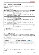
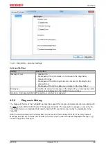
4.5.7
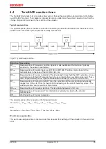
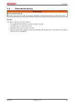
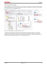
Diag History tab
All errors occurring within the TwinSAFE components are stored in their diag history. The diag history can be
viewed by selecting the corresponding TwinSAFE component in the I/O tree structure and then selecting the
Diag
History tab. Use the
Update History
button to fetch the current data from the TwinSAFE component.
Errors within the logic, the function blocks, the connections or the component itself are stored with a
corresponding time stamp.
Fig. 30: Diag history
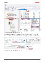
Use the
Advanced…
button to open the advanced settings. Here, the user can customize the behavior of the
diag history.
Summary of Contents for EP1918
Page 2: ......
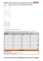
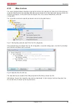
Page 30: ...Operation EP1918 30 Version 1 1 0 Fig 19 Creating alias devices by the user ...
Page 53: ...Appendix EP1918 53 Version 1 1 0 5 3 Certificates ...
Page 55: ......