background image

Appendix

9. The host name is composed by default of "CX" and the last 3 bytes of the MAC address. You can find the
MAC address on the side of the CX80xx. The MAC address is always 6 bytes long and the first three bytes
are the vendor ID, which is always 00 01 05 in the case of Beckhoff devices.

An "X" next to 

Connected

 means that the CX is already known in the system and can be used. To make it

known, click in the list on the CX with which you want to connect and then click on "Add route". An input
mask opens with "User name" and "Password". By default there is no password, simply confirm by clicking
on OK. Afterwards the "X" should appear next to 

connected

.

10. Next, the CX should appear in the list of the devices; select it and confirm by clicking on OK.

11. Check whether the connection is there. In the System Manager in the bottom right-hand corner. It must
be blue or green and may 

not

 be yellow.

12. If the setting is green, switch the CX to Config Mode with "Shift F4" or click on the blue TC icon in the
System Manager. The System Manager now asks you whether you really want to switch to Config Mode;
confirm by clicking on OK.

13. The setting at the bottom right must now change to blue and the TC LED on the CX80xx must now also
light up blue.

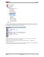
14. Now click on I/O Devices and then on Scan Devices...

15. A message appears, informing you that not everything will be automatically detected.

16. The CCAT interface is usually found (CX8090) or the corresponding fieldbus interface (other CX80xx
devices) and either a K-bus interface or an EtherCAT interface, depending now on which terminals you have
connected to the CX. The CCAT interface must be present in the System Manager file and may not be
deleted. If an error message should appear when scanning, check the revision level of your TwinCAT
version and perform an update if necessary.

CX8080

62

Version: 1.0.0

Summary of Contents for CX8080

Page 1: ...Documentation CX8080 Embedded PC with RS232 RS485 Interface 1 0 0 20 05 2016 Version Date...

Page 2: ......

Page 3: ...ting the IP adress 21 4 2 1 IP address 21 4 2 2 Setting the address via DHCP server 22 4 2 3 Subnet mask 22 4 3 Configuration 23 4 3 1 CX80xx Operating system 23 4 3 2 Power supply terminal 25 4 3 3 R...

Page 4: ...between Modbus and ADS 50 6 3 TCP IP 52 6 4 ADS Communication 53 7 Serial interface 55 7 1 RS232 RS485 system overview 55 7 2 ZB3180 55 8 Error handling and diagnosis 57 8 1 Diagnostic LEDs 57 9 Appen...

Page 5: ...ns in this documentation Trademarks Beckhoff TwinCAT EtherCAT Safety over EtherCAT TwinSAFE XFC and XTS are registered trademarks of and licensed by Beckhoff Automation GmbH Other designations used in...

Page 6: ...n of symbols In this documentation the following symbols are used with an accompanying safety instruction or note The safety instructions must be read carefully and followed without fail DANGER Seriou...

Page 7: ...Foreword Image Version CX8080 Requirements Firmware Description Build 2248 First version required TwinCAT version 2 11 R3 build 2249 CX8080 7 Version 1 0 0...

Page 8: ...interfaces with switch functions so that a linear daisy chain topology can be constructed inexpensively without additional hardware The other connections on the lower plug level are fieldbus specific...

Page 9: ...er is programmed according to the high performance IEC 61131 3 standard As with all other Beckhoff controllers the TwinCAT automation software is the basis for parameterization and programming Users t...

Page 10: ...ot overloaded CX8080 The CX8080 is a controller with an Ethernet port and two serial interfaces From TwinCAT 2 11 R3 build 2249 the Ethernet port is used for programming and or configuration The seria...

Page 11: ...CE 6 0 Programming TwinCAT PLC Programming languages IEC 61131 3 Online Change Yes Up download code Yes Yes Power supply 24 VDC 15 20 UPS 1 second UPS Power supply for I O terminals max 2 A Max power...

Page 12: ...ustrial applications Use exclusively MicroSD cards approved by Beckhoff Example of a MicroSD card Order identifier Capacity Description CX1900 0123 1 GB MicroSD card SLC memory with extended temperatu...

Page 13: ...mounting rails Snapping onto the mounting rail The CX80xx can simply be snapped onto the mounting rail To this end simply position the block on the mounting rail and push it slightly until it engages...

Page 14: ...nting must provide a clearance of 30 mm both above and below a CX80xx device combination to ensure adequate ventilation of the base CPU module and the power supply unit The high performance and the co...

Page 15: ...Mounting and wiring CX8080 15 Version 1 0 0...

Page 16: ...required for the Bus Terminals This is provided by means of the power contacts which are not connected to the power supply Only 24 V DC may be connected to the power contacts the maximum current load...

Page 17: ...medium for 10Base5 consists of a thick coaxial cable yellow cable with a max transmission speed of 10 Mbaud arranged in a line topology with branches drops each of which is connected to one network d...

Page 18: ...o category 3 and is not recommended for use in an industrial environment S UTP Screened unshielded twisted pair screened with copper braid Has a general screen of copper braid to reduce influence of e...

Page 19: ...Termination resistor Usually no termination resistors are required for low baud rates In situations with long line lengths high line resistance a large number of RS485 devices or high baud rates a te...

Page 20: ...time clock RTC of the CX80xx It ensures that the RTC continues to run in the power off state so that the set time is available again on restarting Step 1 Open the flap Step 2 3 Take a small flat blade...

Page 21: ...tarted 1 on and 2 off The CX mode starts in Config Mode the flash memory or in the case of the CX80xx the SD card is reachable via the USB interface for example for an image update 1 off and 2 on Rest...

Page 22: ...do not use registered IP numbers A subnet mask can be used to subdivide the network with the aid of the mask instead of using a large number of network numbers The subnet mask is a 32 bit number Ones...

Page 23: ...n reboots automatically The CX is then accessible again via CERHOST TELNET TELNET is deactivated by current images on first start up via the registry file Telnet_Disable reg which is located in the fo...

Page 24: ...Server X Print Server SMB CIFS RAS Server PPTP Server Simple Network Management Protocol SNMP X Telnet Server X HTTP ASP FTP SNTP Server X Web Server HTTPD Active Server Pages ASP Support JScript 5 6...

Page 25: ...be faster than 100 ms We recommend a task time of less than 50 ms The K bus update time typically lies between one and five ms Bit 0 K Bus Err Bit 1 Terminal State Err Bit 2 Process Data Length Err B...

Page 26: ...arameterization and commissioning Note DC Distributed Clocks The CX80xx series is not suitable for the use of EtherCAT slaves that use or need distrib uted clocks functionality CX8080 26 Version 1 0 0...

Page 27: ...Manager In the simplest case the CX8080 is scanned and it then adds the two serial interfaces automatically in your system Start your CX8080 in Config mode The TC LED of the CX8080 must then turn blue...

Page 28: ...fosys beckhoff com content 1033 cx8080_hw Resources zip 2495103243 zip Protocols KS8000 protocol for operation of the Bus Coupler BK8100 or BK8000 Both interfaces can be used as BK8xx0 master It is an...

Page 29: ...de It should be used for all other protocols In conjunction with the supplements ModbusRTU IEC 60870 or other serial protocols the interface can then support different serial protocols Proprietary pro...

Page 30: ...ages There is a Upnp webpage on the CX80xx for diagnostics User name guest Password 1 Enter the IP address or the device name Example http cx 0f94ac config http 172 16 17 55 config The diagnostic page...

Page 31: ...is can be prepared and activated with the help of the PLC Control in TwinCAT The call is made via the IP address or the device name in a web browser Further information can be taken from the documenta...

Page 32: ...quired on the PC Windows NT Windows 2000 Windows XP or Windows 7 Microsoft Remote Display CERHOST available license free from Microsoft Establishing the connection The Remote Display tool is started o...

Page 33: ...g of the persistent data only takes place in conjunction with the function block FB_S_UPS_CX80xx This block must be called cyclically We strongly recommend using the default values for the block Savin...

Page 34: ...managing the persistent data Other applica tions are not supported and are not covered by our complaints procedure Retain data can not be used for the 1 second UPS 4 3 7 CPU load In the delivery cond...

Page 35: ...does not have sufficient capacity for bridging power failures Saving can take place only on Micro SD cards A QuickShutdown is performed automatically in the eSUPS_WrPersistData_Shutdown mode standard...

Page 36: ...of the persistent data and then QuickShutdown See E_S_UPS_Mode ePersistentMode Mode for the writing of the persistent data Standard value is SPDM_2PASS SPDM_2PASS all persistent data are saved at onc...

Page 37: ...rogramming Prerequisites Development environ ment Target platform Hardware PLC libraries to be linked TwinCAT v2 11 0 build 2220 or higher R3 ARM Seconds UPS TcSystemCX80xx lib CX8080 37 Version 1 0 0...

Page 38: ...g fehlerhaft steht nur einen Zyklus an eSUPS_WritePersistentData im Modus eSUPS_WrPersistData_Shutdown Schreiben der Persistenten Daten ist aktiv im Modus eSUPS_WrPersistData_NoShutdown Schreiben der...

Page 39: ...ddress to the CX8080 CX809xor if you are using the RT Ethernet with bus couplers such as the BK9000 you can display whether all BK9000s are in data exchange Possible colors are red and green The F_CX8...

Page 40: ...809x or if you are using the RT Ethernet with bus couplers such as the BK9000 you can display whether all BK9000s are in data exchange Possible colors are red and green The F_CX8090_LED_ERR function u...

Page 41: ...h this function the address selection switch or the DIP switch of the CX80xx device can be read out Here for example you can activate different parts of the program depending on the address by reading...

Page 42: ...data array The control byte is written by the PLC program and acknowledges the sending of data with the TR bit Toggling the bit edge change results in sending of the number of data length of the data...

Page 43: ...acknowledges receipt of data by changing the state of this bit Only then new data can be transferred from the interface to the controller CW 0 TR TransmitRequest toggle Via a change of state of this...

Page 44: ...has to acknowledge receipt of the data in the control word via a change of state of bit CW 1 RA Only then new data can be transferred from the interface to the controller SW 0 TA TransmitAccepted tog...

Page 45: ...for example be used for the BootP protocol in order to set the TCP IP number This involves sending a telegram containing the information such as the name or the TCP IP number to the corresponding nod...

Page 46: ...rotocols can run on top of TCP IP or UDP ADS ModbusTCP Both of these protocols are implemented in parallel on the Bus Coupler so that no configuration is needed to activate the protocols ADS can be us...

Page 47: ...le Note Observe system load Observe the system load of your CX8080 when using further Ethernet protocols such as ModbusTCP UDP or WebServices A high load can slow down Ethernet communication significa...

Page 48: ...com content 1031 tcmodbussrv html tcmodbussrv_overview htm English http infosys beckhoff com content 1033 tcmodbussrv html tcmodbussrv_overview htm Note CX8091 The Modbus TCP server is not part of the...

Page 49: ...ve to be configured by the user TCP port number The TCP port number for ModbusTCP has been standardized to 502 Modbus Unit The unit is returned by the slave ModbusTCP Protocol Byte Name Description 0...

Page 50: ...tput registers 0x0000 0x2FFF Index group Index offset 0xF030 process image of the physical outputs 0x0 0x3000 0x5FFF 0x4020 PLC memory area 0x0 0x6000 0x7FFF 0x4040 PLC data area 0x0 0x8000 0x80FF Nam...

Page 51: ...33023 EndAddress VarName mb_Input_Registers VarName MappingInfo InputRegisters OutputRegisters MappingInfo AdsPort 801 AdsPort StartAddress 0 StartAddress EndAddress 12287 EndAddress IndexGroup 61488...

Page 52: ...ntent 1031 tcpipserver html tcpipserver_overview htm English http infosys beckhoff com content 1033 tcpipserver html tcpipserver_overview htm Note CX8091 The TCP IP server is not part of the image of...

Page 53: ...route to communicate with all the connected devices and to parameterize them Outside the Beckhoff system a variety of methods are available to exchange data with other software tools Software interfac...

Page 54: ...1 05 01 02 03 AMSNetID 5 1 2 3 1 1 Port number The port number distinguishes sub elements in the connected device Port 801 local process data PLC runtime 1 Index group The index group distinguishes di...

Page 55: ...RS485 CX8080 Number of I O modules 4 Transmission medium screened copper cable 2 x 0 25 mm Cable length 200 m Data transfer rate 300 baud 115 kbaud Topology Line topology 7 2 ZB3180 A D sub connector...

Page 56: ...on class IP20 Connector 9 pin D sub connector straight or angled cable connection Material Thermoplastic black Permissible ambient temperature range during operation 0 C 55 C Dimensions 48 x 50 x 19 m...

Page 57: ...D yellow flashing Activity LED coupler Labelling Meaning Color Meaning TC Displays the TwinCAT mode red TwinCAT in Stop Green TwinCAT in Running Mode Blue TwinCAT in Config Mode WD no function ERR Err...

Page 58: ...24 V top right 1st row Power contacts supply voltage connected to 24 V 3 L A left center 2nd row EtherCAT LED flashing green EtherCAT communication active connected to E bus no data traffic not connec...

Page 59: ...Bus Terminal is located 4 pulses 0 K Bus data error break behind the Bus Coupler Check whether the n 1 Bus Terminal is correctly connected replace if necessary n Break behind Bus Terminal n Check whet...

Page 60: ...oltage to the CX80xx see power supply 16 3 Connect Ethernet CX80xx X001 to your network or a direct connection to your PC make sure in the case of a peer to peer connection that the IP addressing in y...

Page 61: ...Your network is scanned for Beckhoff controllers If none is found this means that the DHCP of the controller is not yet completed or the network settings on your PC are incorrect A network cable that...

Page 62: ...m right hand corner It must be blue or green and may not be yellow 12 If the setting is green switch the CX to Config Mode with Shift F4 or click on the blue TC icon in the System Manager The System M...

Page 63: ...anslate the program If it is error free a warning must come that it is OK save the project under an arbitrary name translate it again and save it once again 18 Switch once again to the System Manager...

Page 64: ...election of the target system select the correct CX click on it and select runtime system 1 Now Online login again F11 transfer the PLC program then Online Start F5 The LED on your terminal must now f...

Page 65: ...image Always copy all files and directories in order to update a CX80xx Update via USB A USB cable is required for this Switch off the CX80xx Set red Dip switch under the flap DIP 1 to ON Switch on th...

Page 66: ...roSD card into the reader Delete all files we recommend that you backup all files first no formatting Load the new image Wait until copying has finished then remove the MicroSD card Insert the MicroSD...

Page 67: ...adquarters Beckhoff Automation GmbH Co KG Huelshorstweg 20 33415 Verl Germany Phone 49 0 5246 963 0 Fax 49 0 5246 963 198 e mail info beckhoff com Beckhoff Support Support offers you comprehensive tec...

Reviews: