background image

Notes on the documentation

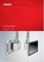
CP37xx-1600

5

Version: 1.1

1

Notes on the documentation

This description is only intended for the use of trained specialists in control and automation engineering who
are familiar with the applicable national standards.

The following instructions and explanations must be followed during installation and commissioning of the
components. The responsible staff must ensure that the application or use of the products described satisfy
all the requirements for safety, including all the relevant laws, regulations, guidelines and standards.

Disclaimer

The documentation has been prepared with care. The products described are, however, constantly under
development. For that reason the documentation is not in every case checked for consistency with
performance data, standards or other characteristics. In the event that it contains technical or editorial errors,
we retain the right to make alterations at any time and without warning. No claims for the modification of
products that have already been supplied may be made on the basis of the data, diagrams, and descriptions
in this documentation. All illustrations shown are only examples. The configurations depicted may deviate
from the standard.

Trademarks

Beckhoff

®

, TwinCAT

®

, TwinCAT/BSD

®

, TC/BSD

 ®

, EtherCAT

®

, EtherCAT G

®

, EtherCAT G10

®

, EtherCAT P

®

,

Safety over EtherCAT

®

, TwinSAFE

®

, XFC

®

, XTS

®

 and XPlanar

®

 are registered and licensed trademarks of

Beckhoff Automation GmbH.
Other designations used in this publication may be trademarks whose use by third parties for their own
purposes could violate the rights of the owners.

Patents

The EtherCAT Technology is covered, including but not limited to the following patent applications and
patents: EP1590927, EP1789857, EP1456722, EP2137893, DE102015105702 with the corresponding
applications and registrations in various other countries.

Copyright

© Beckhoff Automation GmbH & Co. KG. Publication of this document on websites other than ours is
prohibited. Offenders will be held liable for the payment of damages. All rights reserved in the event of the
grant of a patent, utility model or design.

Delivery state

All the components are supplied in particular hardware and software configurations appropriate for the
application. Changes to the hardware or software configuration are permitted, provided they are within the
specified limits for power consumption and power dissipation (please refer to the respective data sheet).

Delivery conditions

In addition, the general delivery conditions of the company Beckhoff Automation GmbH & Co. KG apply.

Summary of Contents for C9900-G050

Page 1: ...Manual EN CP37xx 1600 Multi touch Panel PC 9 15 2021 Version 1 1...

Page 2: ......

Page 3: ...3 3 5 USB 18 3 4 Name plate 19 3 5 Connecting cable 20 4 Commissioning 22 4 1 Transport and storage 23 4 2 Mounting 24 4 2 1 Dimensions 27 4 2 2 Mounting arm tube installation 31 4 2 3 Installing a to...

Page 4: ...Table of contents CP37xx 1600 4 Version 1 1 10 1 Service and support 51 10 2 Approvals 52...

Page 5: ...figurations depicted may deviate from the standard Trademarks Beckhoff TwinCAT TwinCAT BSD TC BSD EtherCAT EtherCAT G EtherCAT G10 EtherCAT P Safety over EtherCAT TwinSAFE XFC XTS and XPlanar are regi...

Page 6: ...l lead to death or serious injuries WARNING Disregarding the safety notice may lead to death or serious injuries CAUTION Disregarding the safety notice may lead to minor injuries Warning of damage to...

Page 7: ...on and power dissipation please refer to the respective data sheet Ensure that only trained specialists with a control and automation technology background operate the device Use by unauthorized perso...

Page 8: ...inch 1366 x 768 19 inch 1280 x 1024 21 5 inch 1920 x 1080 24 inch 1920 x 1080 The device has a multi finger touch screen and an aluminum housing with all round IP65 protection The housing surface is...

Page 9: ...Product overview CP37xx 1600 9 Version 1 1 1 2 Fig 1 CP37xx 1600_with and without push button extension...

Page 10: ...nting arm tube Mounting arm tube for installation from below or above 2 USB interface under screw cap Connection of peripheral devices 3 Name plate Information on the equipment of the Panel PC 4 Optio...

Page 11: ...a mounting arm adapter on the Panel PC you first have to gain access to the connection compartment of the device Follow the steps below as shown in Fig 3 1 Use a screwdriver to reach into the recesse...

Page 12: ...gative pole Supply voltage 24 V 6 5 24 V Positive pole Supply voltage 24 V 7 6 PC ON Input PC_ON 8 7 P S Power Status output minus is the negative pole of the supply voltage 9 NC not used 10 NC not us...

Page 13: ...is 100 m The Ethernet port is suitable for cycle times 1 ms and for distributed clock applications with EtherCAT An Intel i210 is used as controller 1 8 X10² Fig 5 CP37xx 1600_Ethernet interface pin...

Page 14: ...ces with USB connection The interface is located behind a screw cap It supplies 900 mA current and is electronically fused 1 2 3 4 5 6 9 78 Fig 6 CP37xx 1600_USB interface pin numbering Table 5 USB in...

Page 15: ...d are installed ex factory 3 3 1 Ethernet RJ45 The additional optional Ethernet RJ45 interfaces in the form of Harting push pull built in sockets enable the connection of appropriate network component...

Page 16: ...or operation 7 RTS Signal out Request to Send 8 CTS Signal in Clear to Send 9 RI Signal in Ring Indicator 3 3 3 RS422 The optional RS422 serial interface includes an electrically isolated M12 IP65 soc...

Page 17: ...f an overvoltage occurs the channel is switched off 1 2 3 4 5 6 7 8 9 10 11 12 Fig 10 CP37xx 1600_RS485 interface pin numbering Table 10 RS485 pin assignment Pin Signal Type Description 1 2 TxD Data O...

Page 18: ...ng options are available Table 12 Ordering options for USB interfaces Options Description C9900 E283 IP 65 connector for USB 3 0 port Harting push pull USB 3 0 socket C9900 E190 USB A socket for USB 2...

Page 19: ...number BTN 3 Date of manufacture 4 Mainboard 5 CPU 6 RAM 7 Storage media 8 Hard disk 9 MAC addresses of the Ethernet interfaces 10 Power supply 24 VDC NEC class 2 11 Symbols Note Here you will find t...

Page 20: ...for CP32xx CP37xx and CP72xx length 5 m pre assembled Harting push pull Ethernet connector IP 65 second end RJ45 IP 20 C9900 K283 Network cable for CP32xx CP37xx and CP72xx length 10 m pre assembled H...

Page 21: ...n 1 1 Connection cable Serial interface cable RS232 with IP 65 connector C9900 K297 Serial interface cable RS232 for CP32xx CP37xx or CP72xx length 10 m pre assembled M12 plug connector IP 65 screw ty...

Page 22: ...ctive film for Panel PCs and Control Panels with 19 inch display for fitting onto the glass pane 1 item C9900 T231 Adhesive protective film for Panel PCs and Control Panels with 21 5 inch display for...

Page 23: ...e device must therefore be protected from mechanical stress Appropriate packaging of the Panel PC in particular the original packaging can improve the vibration resistance during transport NOTE Hardwa...

Page 24: ...ltable mounting arm adapter for CP37xx 1xxx Figure 13 shows the two available mounting arm adapters Both adapters have a locking screw to prevent rotation Ordering option 1 has an additional clamping...

Page 25: ...section A For the exact procedure see chapter 3 2 Interface description 11 2 Place the mounting arm adapter with the four M6 screws in front of the four M6 threaded holes at the back of the Panel PC s...

Page 26: ...issioning CP37xx 1600 26 Version 1 1 Fig 16 CP37xx 1600_mounting arm adapter installed A strain relief plate is located inside the mounting arm adapter You can relocate this according to your requirem...

Page 27: ...5 inch Panel PC 325 2 100 100 179 3 37 5 63 5 360 8 282 3 3 75 142 7 Fig 17 CP3715 1600_dimensions Fig 18 shows the dimensions of the 15 6 inch Panel PC 37 5 67 5 405 8 250 9 100 100 325 2 75 3 142 7...

Page 28: ...dimensions Fig 20 shows the dimensions of the 18 5 inch Panel PC 3 75 142 6 9 471 8 289 6 37 5 64 5 325 2 100 100 179 3 Fig 20 CP3718 1600_dimensions Fig 21 shows the dimensions of the 18 5 inch Panel...

Page 29: ...2 7 3x M5 6H 433 2 356 37 5 66 5 100 325 2 100 179 3 Fig 22 CP3719 1600_dimensions Fig 23 shows the dimensions of the 21 5 inch Panel PC 7 3 75 142 537 2 321 7 37 5 65 5 100 325 2 179 3 100 Fig 23 CP3...

Page 30: ...n dimensions Fig 25 shows the dimensions of the 24 inch Panel PC 6 9 3 75 142 592 2 352 2 325 2 179 3 100 100 37 5 65 5 Fig 25 CP3724 1600_dimensions Fig 26 shows the dimensions of the 24 inch Panel P...

Page 31: ...unting arm tube has to be installed on the adapter in the same direction Among other tools you need a hook wrench for the installation You can order this from your Beckhoff Sales using the following o...

Page 32: ...num mounted on the underside of a Control Panel or Panel PC CP3xxx can only be ordered together with the Control Panel or Panel PC C9900 M419 Toolboard for keyboard or tools mounted on the underside o...

Page 33: ...6 4 1 b stipulates that one side of the circuit or a point of the energy source for this circuit must be connected to the protective conductor system Devices connected to the Panel PC with their own p...

Page 34: ...to material damage due to electromagnetic in terference Only use the device with functional earth Electromagnetic compatibility EMC of the Panel PC includes on the one hand not affecting other devices...

Page 35: ...the power supply Cables with a maximum cable cross section of 1 5 mm2 can be used for connecting the power supply For long supply lines use 1 5 mm2 cables to achieve a low voltage drop on the supply...

Page 36: ...ficantly shortens the life of the battery Avoid switching off the power supply before shutting down the operating system Use the Beckhoff concept see below to shut down the operating system in a batte...

Page 37: ...owing link https download beckhoff com download software Industrial_PC OS_Support Driver_DVD or you can contact Beckhoff Service service beckhoff com which will provide you with the software and drive...

Page 38: ...of using the Beckhoff Device Manager to remotely configure the Industrial PC via a web browser More detailed information is available in the Beckhoff Device Manager manual First start Beckhoff Device...

Page 39: ...ng passwords are an important prerequisite for a secure system Beckhoff supplies the device images with standard user names and standard passwords for the operating system It is imperative that you ch...

Page 40: ...erstorm can lead to electric shock Never disconnect the cables of the Panel PC during a thunderstorm Before removing the Panel PC follow the steps below 1 Shut down the Panel PC 2 Gain access to the c...

Page 41: ...wrench size 58 62 in counterclockwise direction section B The ordering option for the hook wrench can be found in chapter 4 2 2 Mounting arm tube installation 31 3 Pull the mounting arm tube out of th...

Page 42: ...sioning CP37xx 1600 42 Version 1 1 A B Fig 34 CP37xx 1600_removing the mounting arm adapter Disposal of the Panel PC When disposing of the Panel PC be sure to observe the national electronic waste reg...

Page 43: ...lass IP65 Never use compressed air to clean the PC Maintain an ambient temperature range of 0 C to 45 C Cleaning agents In order to avoid damage to the front of the Panel PC during cleaning you must u...

Page 44: ...he front panel Fig 35 CP37xx 1600_ Cleaning Mode selection You can set the duration for which the PC should remain in Cleaning mode The period can be set between 5 and 120 seconds Right click the sun...

Page 45: ...intervals years UPS battery pack 5 years 2 5 inch hard disk 5 years or after 20 000 operating hours at more than 40 C or after 30 000 operating hours at less than 40 C 3 5 inch hard disk 5 years irre...

Page 46: ...ccess to battery and storage medium To be able to replace the battery and the storage medium you must first gain access to these device components You can access the battery and the storage medium via...

Page 47: ...displayed incorrectly Table 24 Technical data of the battery Battery type Electrical properties at 20 C Dimensions Nominal voltage Nominal capac ity Diameter Height Weight CR2032 3 0 V 225 mAh 20 0 mm...

Page 48: ...n keep the flash drive as a backup copy For this purpose the BST USB flash drives with SLC flash are designed for a particularly long data preservation For more information on the function of the BST...

Page 49: ...properly The cause of the error is the software or plant parts outside of the Panel PC Call the machine or software manufacturer The Panel PC only works partially or only temporarily e g dark image o...

Page 50: ...esistance sinusoidal vibration EN 60068 2 6 10 to 58 Hz 0 035 mm 58 to 500 Hz 0 5 G 5 m s2 Shock resistance shock EN 60068 2 27 5 G 50 m s2 duration 30 ms EMC interference immunity conforms to EN 6100...

Page 51: ...ich can be found on the name plate Beckhoff Support Support offers you comprehensive technical assistance helping you not only with the application of individual Beckhoff products but also with other...

Page 52: ...against adverse interference if the device is used in a commercial environment This device generates uses and may emit radio frequency energy and may cause adverse interference with radio communicati...

Page 53: ...P3715 1600_dimensions 27 Fig 18 CP3716 1600_dimensions 27 Fig 19 CP3716 1600_push button extension dimensions 28 Fig 20 CP3718 1600_dimensions 28 Fig 21 CP3718 1600_push button extension dimensions 28...

Page 54: ...able 11 RS485 standard configuration 17 Table 12 Ordering options for USB interfaces 18 Table 13 USB interface pin assignment 18 Table 14 Legend for CP37xx 1600 name plate 19 Table 15 Power supply cab...

Page 55: ......

Page 56: ...Beckhoff Automation GmbH Co KG H lshorstweg 20 33415 Verl Germany Phone 49 5246 9630 info beckhoff com www beckhoff com More Information www beckhoff com cp37xx 1600...

Reviews: