background image

Commissioning

C6915

17

Version: 2.0

4.2

Installation in the control cabinet

NOTE

Incorrect installation

Mounting the device in a way that deviates from the documentation can impair its functionality.

• Mount the device only in the orientations shown in the documents.

The C6915 Industrial PC is designed for installation in control cabinets in machine and plant technology.
Please observe the environmental conditions prescribed for the operation (see Chapter 9 

Technical data

[

}

 38]

).

Using different mounting plates, you can align the cable entry based on the application requirements.

Figure 8 shows the two available mounting plates: the standard mounting plate 1 and the optional mounting
plate 2. Mounting plate 1 in mounted on the rear panel of the Industrial PC and mounting plate 2 on the right-
hand side panel. In both cases, four M4 x 8 countersunk head Philips screws are used for mounting.

1

2

Fig. 8: C6915_Mounting plates

In the basic equipment version, the Industrial PC is delivered with mounting plate 1 already mounted as
shown in fig. 8. Mounting plate 2 is not included in the scope of delivery. You can choose the following
ordering options:

• C9900-M653: Mounting plate on the side panel instead of on the rear panel

Summary of Contents for C6915

Page 1: ...Manual EN C6915 Industrial PC 6 29 2021 Version 2 0 ...

Page 2: ......

Page 3: ...tion in the control cabinet 17 4 2 1 Dimensions 18 4 2 2 Installation in the control cabinet 19 4 3 Connecting the Industrial PC 20 4 3 1 Installing the supply cable 21 4 3 2 Grounding of the Industrial PC 22 4 3 3 Connecting cables and power supply 23 4 4 Switching the Industrial PC on and off 25 5 Beckhoff Device Manager 27 6 Decommissioning 29 6 1 Disconnecting the power supply and cables 29 6 ...

Page 4: ...Table of contents C6915 4 Version 2 0 ...

Page 5: ...rCAT EtherCAT G EtherCAT G10 EtherCAT P Safety over EtherCAT TwinSAFE XFC XTS and XPlanar are registered and licensed trademarks of Beckhoff Automation GmbH Other designations used in this publication may be trademarks whose use by third parties for their own purposes could violate the rights of the owners Patents The EtherCAT Technology is covered including but not limited to the following patent...

Page 6: ...ath or serious injuries WARNING Disregarding the safety notice may lead to death or serious injuries CAUTION Disregarding the safety notice may lead to minor injuries Warning of damage to property NOTE Disregarding the notice may lead to damage to property 2 2 Intended use The Industrial PC is intended for control cabinet installation and use as a control system in machine construction and plant e...

Page 7: ...issipation please refer to the respective data sheet Ensure that only trained specialists with a control and automation technology background operate the Industrial PC Use by unauthorized persons can lead to damage to property and loss of data Protect the power supply cable with a fuse with a max rating of 16 A The fuse serves to protect the supply line in the event of a short circuit In case of f...

Page 8: ...dustrial PC can be used for the following applications among others diverse automation and visualization tasks wide range of IoT tasks for example when used as an IoT gateway simple HMI applications axis control short cycle times high volume data handling The basic configuration of the C6915 includes the following aspects Intel processor 1 DVI connection graphic adapter integrated in the Intel pro...

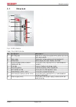
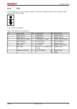
Page 9: ...eldbus hard disk 4 Optional additional Ethernet RJ45 interface X109 Connection of the Industrial PC to a 100 1000BASE T network 5 Front flap Access to battery and storage media 6 Grounding screw Functional earthing of the Industrial PC 7 DVI interface X108 Connection of a DVI capable monitor 8 USB interfaces X104 X107 Connection of peripheral devices 9 RJ45 Ethernet interfaces X102 X103 Connection...

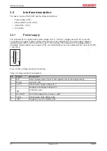
Page 10: ...4 V of the socket If the Industrial PC is equipped with an integrated uninterruptible power supply UPS an external battery pack can additionally be connected to PIN 1 and PIN 2 X101 8 1 P S PC ON 24V 24V UPS BAT C9900 U330 U332 only Fig 2 C6915_Voltage socket pin numbering Table 2 Voltage socket pin assignment Pin Signal Description 8 P S Power Status output minus is the negative pole of the suppl...

Page 11: ...port i210 connected via PCIe is usually suitable for cycle times 1 ms and for distributed clock applications with EtherCAT X102 X103 8 1 1 8 LAN1 LAN2 Fig 3 C6915_Ethernet interface pin numbering Table 4 Ethernet interface pin assignment Pin Signal Description 1 T2 Pair 2 2 T2 3 T3 Pair 3 4 T1 Pair 1 5 T1 6 T3 Pair 3 7 T4 Pair 4 8 T4 The LEDs of the LAN interfaces indicate the activity and the spe...

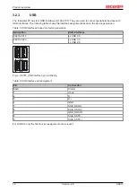
Page 12: ...SB interfaces based on device generation Generation USB interfaces C6915 0010 4x USB 2 0 C6915 0020 2x USB 3 0 2x USB 2 0 1 2 3 4 4 3 2 1 5 6 7 8 9 5 6 7 8 9 1 2 3 4 4 3 2 1 5 6 7 8 9 5 6 7 8 9 4 3 2 1 X10⁴ 107 Fig 4 C6915_USB interface pin numbering Table 6 USB interface pin assignment Pin Connection Shell Shield 1 Vbus 2 D 3 D 4 GND 5 StdA_SSRX 6 StdA_SSRX 7 GND_DRAIN 8 StdA_SSTX 9 StdA_SSTX For...

Page 13: ...n Connection Pin Connection Pin Connection 1 TDMS Data 2 9 TDMS Data 1 17 TDMS Data 0 2 TDMS Data 2 10 TDMS Data 1 18 TDMS Data 0 3 TDMS Data 2 4 Shield 11 TDMS Data 1 3 Shield 19 TDMS Data 0 5 Shield 4 not connected 12 not connected 20 not connected 5 not connected 13 not connected 21 not connected 6 DDC Clock 14 5V Power 22 TDMS Clock Shield 7 DDC Data 15 Ground 5 V Analog H V Sync 23 TDMS Clock...

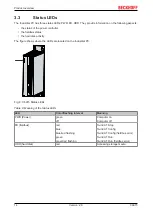
Page 14: ...disk activity The figure shows where the LEDs are located on the Industrial PC Fig 6 C6915 Status LEDs Table 8 Meaning of the Status LEDs LED Color flashing interval Meaning PWR Power green off Computer on Computer off FB fieldbus red blue blue red flashing green green red flashing TwinCAT Stop TwinCAT Config TwinCAT Config fieldbus error TwinCAT Run TwinCAT Run fieldbus error HDD hard disk red Ac...

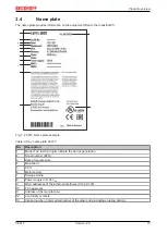
Page 15: ...mple Table 9 Key name plate C6915 No Description 1 Model The last four digits indicate the device generation 2 Serial number BTN 3 Date of manufacture 4 Mainboard 5 CPU 6 Main memory 7 Storage media 8 Power supply unit 24 VDC 9 MAC addresses of the Ethernet interfaces X102 X103 10 FCC approval 11 Address of the manufacturer 12 Conformity symbols 13 Variant number Commercial number of the order cod...

Page 16: ...riate packaging of the Industrial PC in particular the original packaging can improve the vibration resistance during transport NOTE Hardware damage due to condensation Unfavorable weather conditions during transport can cause damage to the device Protect the device against moisture condensation during transport in cold weather or in case of ex treme temperature fluctuations Do not put the device ...

Page 17: ... you can align the cable entry based on the application requirements Figure 8 shows the two available mounting plates the standard mounting plate 1 and the optional mounting plate 2 Mounting plate 1 in mounted on the rear panel of the Industrial PC and mounting plate 2 on the right hand side panel In both cases four M4 x 8 countersunk head Philips screws are used for mounting 1 2 Fig 8 C6915_Mount...

Page 18: ...correctly in the control cabinet All dimensions are in mm Figure 9 illustrates the dimensions of the Industrial PC with mounting plate 1 163 5 120 3 124 3 32 46 48 190 203 Fig 9 C6915_Dimensions with mounting plate 1 Figure 10 illustrates the dimensions of the Industrial PC with mounting plate 2 190 95 2 120 3 10 52 48 163 5 203 Fig 10 C6915_Dimensions with mounting plate 2 ...

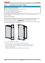
Page 19: ...the mounting plates the control cabinet must be equipped with drill holes for the fastening screws corresponding to the dimensions of the PC see chapter 4 2 1 Dimensions 18 You need M4 screws for mounting After you have drilled the holes for the fastening screws in the control cabinet you can mount the Industrial PC in the control cabinet with the mounting plates Fig 11 C6915_Control cabinet insta...

Page 20: ...device To prepare the Industrial PC for operation it must be connected The first step is to ground the device Then you can connect the cables and the power supply An external power supply unit is required to supply 24 V DC 15 20 for operating the device Wire the Industrial PC in the control cabinet in accordance with the EN 60204 1 2006 standard on Protective Extra Low Voltage PELV so that one sid...

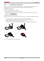
Page 21: ...pin connection strip For the pin assignment of the connector see Chapter 3 2 1 Power supply 10 Assembly of the strain relief housing Now mount the strain relief housing on the already connected connector and supply cable as shown in fig 12 1 Thread the cable tie into the lower part of the strain relief housing section A 2 Insert the connection strip into the lower part of the strain relief housing...

Page 22: ...tective earth PE EMC NOTE Hardware damage due to electromagnetic interference Using the Industrial PC without functional earthing can lead to hardware damage due to electromagnetic in terference Only use the device with functional earthing Electromagnetic compatibility EMC of the industrial PC includes on the one hand not affecting other devices and equipment by electromagnetic interference and on...

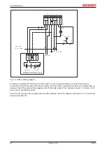
Page 23: ...the maximum possible cross section In case of larger distances between the power source and the PC take into account the voltage drop in relation to the cable cross section as well as fluctuations in your supply voltage in order to ensure that the voltage at the power supply unit does not fall below 22 V Proceed as follows to connect the 24 VDC power supply unit 1 Check the correct voltage of your...

Page 24: ...ram So that the Industrial PC still has a monitor output in case of a power failure a Control Panel can be connected to the UPS output of the power supply unit Even after a power failure there is a voltage of 24 VDC between the UPS output and the negative pole of the battery pack The maximum load is 1 4 A max 2 5 A from year of manufacture 2016 Once the PC has been de energized via the UPS softwar...

Page 25: ...ignificantly shortens the life of the battery Avoid switching off the power supply before shutting down the operating system Use the Beckhoff concept see below to shut down the operating system in a battery friendly manner When the system is switched off or disconnected from its own power supply the Industrial PC is also switched off If you have an Industrial PC with a UPS and simply switch off th...

Page 26: ...oftware and drivers The driver software comes with a detailed help function Call up the help files either directly from the configuration tab by clicking the Help button or start the file under Start Programs Beckhoff UPS software components The method of communication between your PC and the UPS depends on the PC generation The following table provides information about the method of communicatio...

Page 27: ...Beckhoff Device Manager to remotely configure the Industrial PC via a web browser More detailed information is available in the Beckhoff Device Manager manual Starting the Beckhoff Device Manager for the first time When your Industrial PC is booted for the first time the Beckhoff Device Manager also starts automatically for the first time The Security Wizard opens This tells you that you should re...

Page 28: ... passwords are an important prerequisite for a secure system Beckhoff supplies the device images with standard user names and standard passwords for the operating system It is imperative that you change these Controllers are shipped without a password in the UEFI BIOS setup Beckhoff recommends assigning a password here as well Please note the following Passwords should be unique for each user and ...

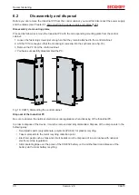
Page 29: ...electric shock Never disconnect the cables from the device during thunderstorms Before you remove the Industrial PC from the control cabinet you must follow the following steps 1 Shut down the operating system 2 Disconnect the Industrial PC from the power supply see below 3 Disconnect the data transfer cables between the Industrial PC and the connected devices see below Disconnect the power supply...

Page 30: ...16 3 Remove the PC from the control cabinet ð You have successfully disassembled the PC Fig 16 C6915_Dismantling the control cabinet Disposal of the Industrial PC Be sure to observe the national electronic scrap regulations when disposing of the Industrial PC In order to dispose of the device it must be removed and fully dismantled Dispose of the components in the following way Send plastic parts ...

Page 31: ...ponents and the replacement of other device components contribute to this Repair Only the manufacturer may repair the device If a repair should be necessary contact Beckhoff Service see Chapter 10 1 Service and support 39 7 1 Cleaning NOTE Unsuitable cleaning agents The use of unsuitable cleaning agents can damage the device Only clean the Industrial PC as specified It is essential to observe the ...

Page 32: ...ervals years UPS battery pack 5 years 2 5 inch hard disk 5 years or after 20 000 operating hours at more than 40 C or after 30 000 operating hours at less than 40 C 3 5 inch hard disk 5 years irrespective of the operating hours Fan 7 years Compact Flash CFast or SSD 10 years Motherboard battery 5 years Beckhoff is excluded from liability in the event of possible damage occurring during maintenance...

Page 33: ...ge For example the following measures can be used Use conductive mats connected to the ground potential as underlays Dissipate possible charges from your own body by touching earthed metal e g control cabinet door Wear a wrist grounding strap Only remove new electronic components from the ESD packaging tinted plastic bag after putting on the wrist grounding strap Do not walk around with electronic...

Page 34: ...st first gain access to these components Access to battery and storage media To get access to the battery and the storage media open the front flap see fig 17 Fig 17 C6915_tool less access to battery and storage media You now have access to the battery 1 and storage media 2 see Fig 18 1 2 2 Fig 18 C6915 _Battery and storage media ...

Page 35: ...o supply power to the clock integrated on the motherboard If the battery is depleted or missing the date and time are displayed incorrectly Table 12 Technical data of the battery Battery type Electrical properties at 20 C Dimensions Nominal voltage Nominal capac ity Diameter Height Weight CR2032 3 0 V 225 mAh 20 0 mm 3 20 mm 3 1 g Chapter 7 2 1 Access to device components 34 shows how to access th...

Page 36: ...to the size of the backup copy of your operating system You can then keep the flash drive as a backup copy For this purpose the BST USB flash drives with SLC flash are designed for a particularly long data preservation For more information on the function of the BST please refer to the corresponding documentation If your storage medium is defective and there is no backup Beckhoff Service can provi...

Page 37: ... PC Other cause Check the power supply cable Call Beckhoff Service The Industrial PC does not boot fully Setup settings are incorrect Other cause Check the setup settings Call Beckhoff Service Computer boots software starts but control does not operate correctly Cause of the fault is either in the software or in parts of the plant outside the Industrial PC Call the machine and software manufacture...

Page 38: ...o 58 Hz 0 035 mm 58 to 500 Hz 0 5 G approx 5 m s2 Shock resistance shock EN 60068 2 27 5 G approx 50 m s2 duration 30 ms EMC interference immunity conforms to EN 61000 6 2 EMC interference emission conforms to EN 61000 6 4 Permissible ambient temperature 0 C to 55 C operation 25 C to 65 C transport storage Permissible air humidity Maximum 95 no condensation Transport and storage The same values fo...

Page 39: ...l PC which can be found on the name plate Beckhoff Support Support offers you comprehensive technical assistance helping you not only with the application of individual Beckhoff products but also with other wide ranging services World wide support design programming and commissioning of complex automation systems extensive training program for Beckhoff system components Hotline 49 0 5246 963 157 F...

Page 40: ... provide adequate protection against adverse interference if the device is used in a commercial environment This device generates uses and may emit radio frequency energy and may cause adverse interference with radio communications if it is not installed and used in accordance with the operating instructions If this device is used in a residential area it is likely to cause adverse interference in...

Page 41: ...ig 9 C6915_Dimensions with mounting plate 1 18 Fig 10 C6915_Dimensions with mounting plate 2 18 Fig 11 C6915_Control cabinet installation 19 Fig 12 C6915_Mounting the strain relief housing 21 Fig 13 C6915_Wiring diagram 24 Fig 14 Beckhoff Device Manager Change Passwords 27 Fig 15 Beckhoff Device Manager Start page 28 Fig 16 C6915_Dismantling the control cabinet 30 Fig 17 C6915_tool less access to ...

Page 42: ...ent 11 Table 5 USB interfaces based on device generation 12 Table 6 USB interface pin assignment 12 Table 7 DVI interface pin assignment 13 Table 8 Meaning of the Status LEDs 14 Table 9 Key name plate C6915 15 Table 10 UPS communication 26 Table 11 Replacement recommendations for PC components 32 Table 12 Technical data of the battery 35 Table 13 Troubleshooting 37 Table 14 Technical data 38 Table...

Page 43: ......

Page 44: ...Beckhoff Automation GmbH Co KG Hülshorstweg 20 33415 Verl Germany Phone 49 5246 9630 info beckhoff com www beckhoff com More Information www beckhoff com C6915 ...

Reviews: