background image

Hazardous moving parts of the drive must be installed at a height of over 2.5 m above floor level or any
other surface from which the drive can be accessed.

To ensure safe operation of the system after commissioning, the limit positions must be correctly set/
programmed in.

Drives with a H05VV-F connecting cable may only be used indoors.

Drives with a H05RR-F, S05RN-F or 05RN-F connecting cable may be used both indoors and outdoors.

To connect the drive to the driven part, solely mechanical accessory components made by the drive
manufacturer from the current product catalogue may be used. The components must be installed in
accordance with the manufacturer's instructions.

If the drive is used for shading solutions in a specially marked area (e.g., escape routes, hazard zones,
safety areas), compliance with all applicable regulations and standards must be ensured.

Caution

Safety instructions for avoiding serious injuries.

When electrical or electronic equipment and units are operated, certain components,

e.g., the power supply unit, are live. Physical injuries or damage to property can result in

the event of unauthorised interventions or failure to heed warnings.

Be careful when touching the tubular drive, as it heats up during operation for technical

reasons.

Before installation, shut down all lines and control devices that are not essential for op-

eration.

Crushing or shearing points must be avoided or protected.

When installing the drive, all-pole disconnection from the mains with a contact gap of at

least 3 mm per pole must be provided (EN 60335).

If the mains connecting cable is damaged, it may only be replaced by the manufacturer.

If the drive has a plug-in connecting cable, it must be replaced with the same type of

mains connecting cable, which is available from the drive manufacturer.

Attention

Safety instructions for avoiding property damage.

Ensure that there is adequate clearance between moving parts and adjacent objects.

The drive must not be carried by the mains connecting cable.

All latching connections and fastening screws on the brackets must be checked to en-

sure that they are secure.

Ensure that nothing rubs against the tubular drive, such as shading solution attach-

ments, screws, etc.

5 - en

Summary of Contents for enocean R8-17

Page 1: ...speeds for roller shutter systems and vertical fabric shades Important information for Fitters Electricians Users Please forward accordingly These instructions must be kept safe for future reference Becker Antriebe GmbH Friedrich Ebert Straße 2 4 35764 Sinn Germany www becker antriebe com 1010 300 002 0g 16 03 2021 ...

Page 2: ...ns using the programming unit 10 Deleting the limit positions using the programming unit 12 Adjusting the limit positions with a rotary switch or a locking button 13 Deleting the limit positions with a rotary switch or a locking button 15 Activating Bluetooth 16 Selecting the driving profile 16 Modifying the zone for slow travel 17 Additional upper anti freeze mechanism 17 Obstacle detection 18 Fl...

Page 3: ...perating Instructions when installing and setting up the equipment The date of manufacture comes from the first four digits of the serial number The numbers 1 and 2 indicate the year and the numbers 3 and 4 indicate the calendar week Example 34th calendar week in 2020 Ser No 2034XXXXX Explanation of pictograms CAUTION CAUTION indicates a hazardous situation which if not avoided could result in inj...

Page 4: ...f safety instructions is not exhaustive since it would be impossible for the standard to include all sources of danger For example the design of the operated product the way the drive works in the situation it is installed in or even the way the end product is mounted in the end user s place of use cannot be taken into consideration by the drive manufacturer If any questions or uncertainties regar...

Page 5: ...e g the power supply unit are live Physical injuries or damage to property can result in the event of unauthorised interventions or failure to heed warnings Be careful when touching the tubular drive as it heats up during operation for technical reasons Before installation shut down all lines and control devices that are not essential for op eration Crushing or shearing points must be avoided or p...

Page 6: ...y for damages or injury arising from such actions Always observe the information in these instructions when operating or repairing the system The drive manufacturer does not ac cept liability for damage or injury resulting from improper usage Attention Only use rigid shaft connectors if the roller shutter laths are sufficiently strong The closed curtain must not project beyond the guide tracks or ...

Page 7: ...ed at the side M and idler G gives the length L of the barrel L X M G The space required at the side M varies depending on the combination of drive and wall bracket Then mount the wall bracket and idler Ensure that the barrel is aligned at right angles to the wall and that sufficient axial play is al lowed for the mounted system Attention When using rigid shaft connectors closed brackets must be f...

Page 8: ...o fit exactly Y X For round shafts Measure the lug of the thrust ring X Y Then notch the tube on the motor side so the lug of the thrust ring can also be pushed into the shaft There must be no play between the lug of the thrust ring and the shaft 10 mm To ensure secure torque transmission for round shafts we recommend screwing the drive adapter to the shaft see the table below Attention When drill...

Page 9: ... fixing Automatic setting of limit positions is possible where a stop system is present on both sides using the rotary switch set Item no 4901 001 158 0 a standard rotary switch or the programming unit for drives with electronic limit switching Item no 4935 200 011 0 All other functions can only be set via the programming unit Connect the wires of the tubular drive to those of the same colour in t...

Page 10: ...d off automatically in the desired position three times If the tubular drive switches off prematurely while opening or closing due to an obstruc tion the obstruction can be cleared by reversing a short way and removing the obstruc tion The desired limit position can then be set by opening closing again When first installing using springs and adjusting the limit position to lower stop the barrel in...

Page 11: ...switches off automatically Then close to the desired lower limit position Press the programming button of the programming unit for 3 seconds The tubular drive acknowledges The limit positions are now set Upper point to lower stop This option for setting the limit positions is not possible with a vertical fabric shade Open to the desired upper limit position Press the programming button of the prog...

Page 12: ... Deleting a limit position when 2 limit positions are programmed Any additional functions that have been set are retained black brown blue green yellow black brown blue green yellow Programming button Travel button Open close to the limit position to be deleted Press the programming button and keep it pressed Then press down the travel button and keep it pressed Now release the programming button ...

Page 13: ...on is then com plete Limit position status indicator A brief stopping and restarting indicates that no limit position has been set in that direction of movement There are several ways to set the limit positions Upper stop to lower stop Upper point to lower point Upper stop to lower point Upper point to lower stop The limit position becomes fixed after the tubular drive has turned off automatically...

Page 14: ...Open to the desired upper limit position Carry out the following sequence without interruption between the individual drive commands The tubular drive confirms until STOP and hold until Then close to the desired lower limit position Carry out the following sequence without interruption between the individual drive commands The tubular drive confirms until STOP and hold until The limit positions ar...

Page 15: ...nent lower stop During travel the limit position status indic ator LSI must be displayed before the limit position is reached The tubular drive switches off automatically The limit positions are now set Deleting the limit positions with a rotary switch or a locking button The switching commands sequence must be carried out in quick succession Carry out the following deletion sequence without inter...

Page 16: ...ll now be visible on the operator unit for 3 minutes Now select the required tubular drive from the list in the Bluetooth menu on your operator unit and click on OK To set up the connection you will now need to enter the PIN code 123456 Selecting the driving profile The limit positions must be set The switching commands sequence must be carried out in quick succession Each completed sequence sets ...

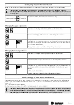
Page 17: ...Open close the shading solution to a point between the limit positions Now move to the bottom point from which you wish to change the speed zone Then firstly push the travel button downwards and then press the programming but ton and keep both buttons pressed down until the lower limit position has been reached The tubular drive confirms The lower zone for slow travel will be set from the next mov...

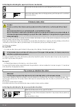
Page 18: ...cking of the lateral guide tracks If the tubular drive switches off in the area of the upper limit position it checks once more whether an obstacle is present To ensure complete closing of the roller shutter curtain at the lower limit position the curtain does not reverse once it gets to ap prox 360 from the lower limit position Moving UP Extremely large increase in the load e g ice on the end str...

Page 19: ... execute simultaneous UP and DOWN com mands Protect the electrical connections from damp Once you have finished wiring everything to the control ALWAYS check the right direction assignment of the drive to the control buttons UP and DOWN EXTEND and RETRACT If the drive is to be operated with devices which contain sources of interference the elec trician must ensure suitable interference suppression...

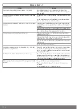
Page 20: ...drive is operational again after a few minutes Tubular drive is faulty does not run even after standing still for a long period of time Replace the tubular drive Clear and remove the obstruction and set the drive in the direc tion required Check the electrical connection During the programming run the drive stops short of the limit position to be programmed For safety reasons the drive reacts sens...

Page 21: ...ack and brown wires according to the direction of travel is de pendant on how the drive is installed mounted to the right or to the left Controlling one several drive s via a single switch button Controls black brown blue green yellow Controls 21 en ...

Page 22: ...ual control using Centronic UnitControl UC42 Mains 230 V 50 Hz Central Group Individual Individual 230 V 50 Hz Central cable connection to further control units 230 V 50 Hz 230 V 50 Hz Electronics 230 V 50 Hz Control unit 22 en ...

Page 23: ...Declaration of conformity 23 en ...

Page 24: ...Declaration of conformity 24 en ...

Page 25: ...permission THIS SOFTWARE IS PROVIDED AS IS AND WITHOUT ANY EXPRESS OR IMPLIED WARRANTIES INCLUDING WITHOUT LIMITA TION THE IMPLIED WARRANTIES OF MERCHANTABILITY AND FITNESS FOR A PARTICULAR PURPOSE BSD 2 Clause Copyright c 1995 Alex Tatmanjants alex elvisti kiev ua at Electronni Visti IA Kiev Ukraine Copyright c 1996 1997 by Andrey A Chernov Moscow Russia Copyright c 1998 M Warner Losh imp freebsd...

Page 26: ...uted to Berkeley by Hugh Smith at The University of Guelph All rights reserved Redistribution and use in source and binary forms with or without modification are permitted provided that the following condi tions are met 1 Redistributions of source code must retain the above copyright notice this list of conditions and the following disclaimer 2 Redistributions in binary form must reproduce the abo...

Page 27: ... copy modify and distribute this file for any purpose is hereby granted without fee provided that the above copyright notice and this notice appears in all copies and that the name of Hewlett Packard Company not be used in advertising or publicity pertaining to distribution of the software without specific written prior permission Hewlett Packard Company makes no representations about the suitabil...

Page 28: ......
Reviews: