BeaconMedaes Lifeline Medical Systems Installation, Operation And Service Manual Download Page 34

34

Part No. 6-847703-00 Rev. C00
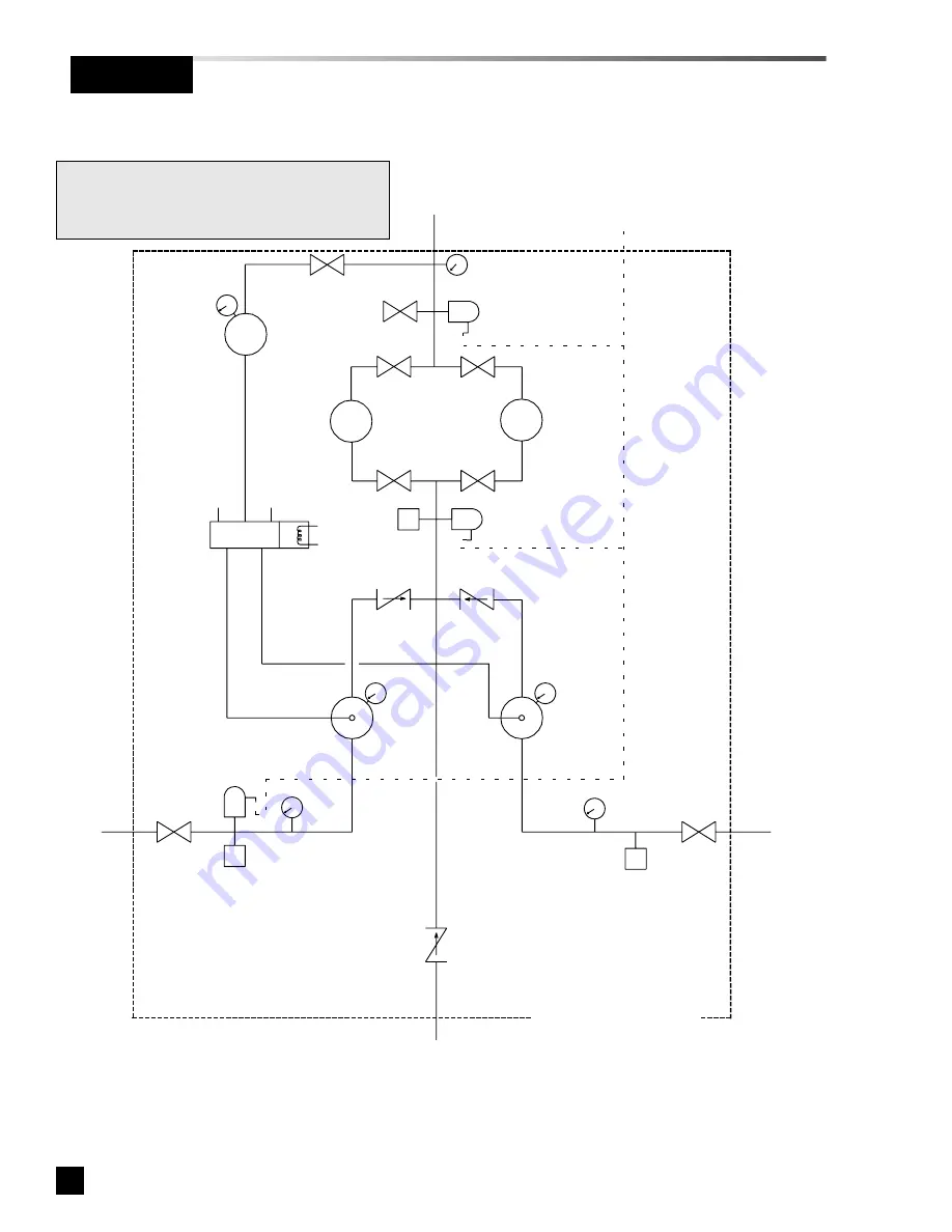
Operation

Figure 22

Manifold

Outlet

Vent Valve

Line Relief Valve

Valve

Line Pressure Gauge

Service Valve

Line

Regulator

Valve

Valve

Valve

Line

Regulator

Intermediate Relief Valve

Solenoid

Valve

Check

Valve

Check

Valve

Bank

Regulator

Bank

Regulator

Inlet

Relief Valve

Bank

Gauge

Bank

Gauge

Check

Valve

*

Dome

Regulator

Relief Valve

Outlet

Right Bank

Inlet

Left Bank

Inlet

From High-Pressure

Reserve Header (Figure 23) 

Manifold Control Panel

* NOTE:

Dome regulators not used on oxygen
manifolds design for 55 PSI delivery pressure.

Secondary Supply

Pressure Switch

Secondary Supply

Pressure Switch

Master

Valve

Master

Valve

Reserve In Use

Pressure Switch

Summary of Contents for Lifeline Medical Systems

Page 1: ...Part No 6 847703 00 Rev C00 Pg 1 Lifeline Medical Systems Fully Automatic Manifold For Use With Liquid Cylinders Installation Operation and Service Manual LQ x HP Liquid x High Pressure Models...

Page 2: ...y Supply Switch Replacement 49 Bank Regulator Replacement 49 Line Regulator Replacement 51 Abbreviations AR Argon CGA Compressed Gas Association CO2 Carbon Dioxide N2 Nitrogen N2O Nitrous Oxide NPTF N...

Page 3: ...ce WARNING Means there is a possibility of injury or death to yourself or others CAUTION Means there is a possibility of damage to unit or other property NOTE Indicates points of particular interest f...

Page 4: ...opriate number of header floor stand kits for manifold s right bank header extensions and reserve header assembly sold separately Manifold System Components Precautions WARNING Tampering with gas spec...

Page 5: ...bracket away from manifold control panel and slide bracket off two upper control panel mounting bolts 3 Mark wall 79 3 4 from finished floor in location where manifold will be mounted Convert mark to...

Page 6: ...r of manifold control inlets to finished floor 5 Mark locations of mounting holes Remove bracket and drill mounting holes Attach bracket to wall with appropriate anchors by others 3 8 diameter anchors...

Page 7: ...7 Part No 6 847703 00 Rev C00 Installation Figure 3...

Page 8: ...ch header extension so they are pointing out away from wall and tighten header extension Figure 4 CAUTION Do not use thread sealant on header or pigtail connections CAUTION Each header segment must be...

Page 9: ...f header extensions two or more header brackets will be provided Header brackets should be positioned along length of high pressure reserve header assembly and should contact header directly between c...

Page 10: ...n Master Valve Nut Plug Reserve Low Pressure Switch Regulator Assembly Figure 7 Nut Plug Header Extensions NOTE Configuration and number of header extensions will vary depending upon size of high pres...

Page 11: ...be required A bracket is provided for each header segment and should contact header between cylinder connections as shown in Figure 9 Top of bracket aligned with horizontal line on wall Above finished...

Page 12: ...ng nut as shown in Figure 1 Pull bottom of bracket away from manifold control panel and slide bracket off two upper control panel mounting bolts 3 Only bracket will be needed at this time Set manifold...

Page 13: ...nch channel is used to mount power supply and may be located on either side of manifold control panel Use flat plate four each 3 8 bolts flat washers and channel nuts Unlike other hardware shown in Fi...

Page 14: ...DETAIL A DETAIL B DETAIL C DETAIL D CAUTION In order to prevent damage to manifold piping connections vertical stands must be securely braced to permanent structure to prevent movement DETAIL E Insta...

Page 15: ...ositioned along length of high pressure reserve header assembly and should contact header directly between cylinder connections Bracket to support control section must be located as shown in Figure 13...

Page 16: ...on outlet side of valve to aid in purging Main Outlet and Relief Valve Connection CAUTION Close 3 4 source shut off valve to prevent debris from falling into manifold during brazing procedure To prev...

Page 17: ...e The fuse type is 5 x 20 mm GMD 250mA 240 VAC models use 0 125 Amp time delay type 5 x 20 mm GMD 125mA Installation Power Supply Installation For connection to a remote alarm or building automation s...

Page 18: ...ound 120 VAC Input Power Secondary Supply Reserve In Use Reserve Low From reserve low switch located on high pressure reserve header Figure 6 7 8 Dry Normally Closed Remote Alarm Contacts 1 2 3 4 5 6...

Page 19: ...nd 16 Secure each cylinder to wall or floor stand with chains or straps 4 Connect pigtails to each cylinder Rigid copper pigtails used on oxygen systems are pre formed to approximate required shape Lo...

Page 20: ...20 Part No 6 847703 00 Rev C00 Figure 15 Figure 16 Installation 72 Flex Pigtail 24 Stainless Steel Flex Pigtail 72 Flex Pigtail Rigid Copper Pigtail...

Page 21: ...ESERVE IN USE and RESERVE LOW alarms are activated 3 Close 3 4 source shut off valve 4 Slowly open one cylinder on high pressure reserve header assembly 1 Release two latches on sides of manifold cove...

Page 22: ...s gauge drops slowly As left contents gauge is nearly depleted manifold changes over to right bank After change over left bank green IN USE light turns off and red EMPTY light illuminates After change...

Page 23: ...23 Wait 15 minutes 24 Compare current readings of manifold left and right gauges and reserve header contents gauge to those recorded in step 19 and 20 If there is a noticeable pressure change on eith...

Page 24: ...lve Vent Valve Line Regulator Isolation Valves Line Regulator Isolation Valves Master Valve Power Supply Connector Master Valve Right Bank Contents Gauge Left Bank Contents Gauge Reserve Header Conten...

Page 25: ...oss of pressure on manifold line pressure gauge indicates a leak downstream of closed line regulator inlet isolation valves A loss of pressure on left manifold contents gauges indicates a leak in comp...

Page 26: ...l be prohibited Do not alter remove or modify gas specific connections Before connecting liquid container to left bank of manifold or high pressure cylinder to right bank of manifold and reserve heade...

Page 27: ...drop 500 10 400 10 500 10 500 10 Reserve In Use Switch on pressure drop 80 5 210 5 210 5 210 5 Reserve Low Switch on pressure drop 1500 25 400 25 1500 25 1500 25 Reserve Header Regulator 70 200 200 20...

Page 28: ...15 18 20 23 26 29 32 37 41 44 48 52 55 Delivery Flow scfm Delivery Pressure psig Operation Flow Characteristics at 300 psig Inlet with 100 psig Delivery 0 10 20 30 40 50 60 70 80 90 100 110 0 8 10 12...

Page 29: ...by flow capacity of liquid container s Approximate maximum continuous gaseous flow of liquid containers are listed below Gas Type Flow per container Oxygen 5 8 scfm 350 scfh Nitrous Oxide 1 8 scfm 110...

Page 30: ...tors in event of an overpressure condition caused by bank regulator or high pressure reserve header regulator failure Outlet of relief valve is piped to a common relief valve port on top of manifold R...

Page 31: ...ill open Activation of switch indicates that contents of high pressure cylinders has been partially depleted either by use or leakage Front Panel Indicators Six front panel indicators monitor status o...

Page 32: ...ulator Dome Regulator Bank Regulator Bank Regulator Line Relief Valve Intermediate Relief Valve Check Valve Line Regulator Isolation Valve Line Regulator Isolation Valve Line Regulator Isolation Valve...

Page 33: ...olenoid Valve Left Bank Pressure Gauge Right Bank Pressure Gauge Line Pressure Gauge NOTE Some components not shown for clarity Figure 21 Reserve Header Master Valve Reserve Header High Pressure Regul...

Page 34: ...heck Valve Bank Regulator Bank Regulator Inlet Relief Valve Bank Gauge Bank Gauge Check Valve Dome Regulator Relief Valve Outlet Right Bank Inlet Left Bank Inlet From High Pressure Reserve Header Figu...

Page 35: ...03 00 Rev C00 Operation Figure 23 High Pressure Regulator Reserve Low Pressure Switch Master Valve Check Valves High Pressure Cylinder Pigtails To Manifold Control Panel Figure 22 High Pressure Reserv...

Page 36: ...PSI Outputs of both left and right bank regulators each pass through check valves and connect together upstream of a dual line regulator assembly An intermediate relief valve protects components betwe...

Page 37: ...and pressure is restored manifold will automatically switch back to left bank Solenoid valve will deenergize and direct dome bias back to left dome regulator Right bank green IN USE light will turn of...

Page 38: ...on power supply box are NOT illuminated If manifold is connected to a master alarm panel SECONDARY SUPPLY RESERVE IN USE and RESERVE LOW alarms are NOT activated 6 If manifold is equipped with a dome...

Page 39: ...ndicated in Table 1 intermediate pressure in use bank If pressure is not correct refer to Bank Regulator Adjustment procedure 16 Verify front panel line pressure gauge reading is the same as in step 9...

Page 40: ...o a master alarm panel SECONDARY SUPPLY and RESERVE IN USE alarms remain activated 27 Slowly open one high pressure cylinder on right side of manifold Verify the following Power supply red RESERVE IN...

Page 41: ...all high pressure cylinders connected to high pressure reserve header 7 Open vent valve to vent all pressure from manifold 8 Close vent valve and slowly open one liquid container or high pressure cyl...

Page 42: ...e 24 Figure 25 B A NOTE Some components not shown for clarity Switches Shunt NOTE When circuit board shunt is installed LQ x HP models only manifold will default to left bank liquid containers as prim...

Page 43: ...p of small screwdriver into adjustment barrel and rotate barrel Figure 26 Line Regulator Adjustment The following procedure describes process of setting line regulator pressure This procedure should o...

Page 44: ...rotate barrel Figure 26 See NOTE above 9 Slowly open one high pressure cylinder on right bank of manifold 10 Repeat steps 3 through 9 until pressure switch has been set within acceptable limits NOTE W...

Page 45: ...ustment barrel and rotate barrel Figure 26 NOTE When viewing switch from wire end rotating barrel clockwise will raise switch setting A counterclockwise rotation will lower switch setting Make small a...

Page 46: ...pressure cylinder on reserve header and adjust vent valve so that high pressure gauge on reserve header regulator drops very slowly 6 Note high pressure gauge reading when red RESERVE LOW light on pow...

Page 47: ...ifold parts tools and work surfaces free of oil grease and dirt These and other flammable materials may ignite when exposed to high pressure oxygen or nitrous oxide Use only proper repair tools and pa...

Page 48: ...e felt indicating ferrule is being resprung into sealing position Then tighten nut 1 12 of a turn 1 2 of a wrench flat past original position If tightening a fitting for first time make sure tube has...

Page 49: ...outer wire screens Take care not to dislodge filter or screens Service Procedures Secondary Supply Switch Replacement The following procedure describes process of replacing secondary supply pressure...

Page 50: ...trol board Carefully unscrew pressure switch and allow wires to twist Removal of switch typically requires 4 5 revolutions When reinstalling switch twist wires 4 5 revolutions in a counterclockwise di...

Page 51: ...nion nuts NOTE Before removing fittings from old regulator note orientation and depth of fitting in regulator body In order to align with isolation ball valves fittings must be installed into new regu...

Page 52: ...from reserve header by loosening zero clearance o ring sealed union on output side of reserve header regulator 4 After all pressure has been vented remove reserve low pressure switch from elbow fitti...

Page 53: ...cabinet 10 Verify correct operation of new control board by performing Performance Verification Control Board Replacement Service Procedures Reserve Low Switch Replacement The following procedure des...

Page 54: ...HP reserve header AC INPUT POWER LINE NEUTRAL GROUND BLACK PIN 5 WHITE PIN 6 RED PIN 3 BROWN PIN 7 BLUE PIN 1 GREEN PIN 2 BLACK PIN 5 WHITE PIN 6 RED PIN 3 BROWN PIN 7 GREEN PIN 2 BLUE PIN 1 BLACK BL...

Page 55: ...e 300 PSI 7 6 130117 00 Bank Pressure Gauge 3000 PSI 8 6 515601 00 Female Connector 1 8 Tube x 1 4 NPT 9 6 513011 00 Reducing Coupler 1 8 NPT x 1 4 NPT 10 6 515602 00 Male Connector 1 8 Tube x 1 8 NPT...

Page 56: ...230764 00 Inlet Relief Valve 400 PSI 25 6 355010 UB Copper U Tube 5 8 OD 26 6 515629 00 Male Elbow 1 8 Tube x 1 4 NPT 27 6 515605 00 Male Connector 1 8 Tube x 1 4 NPT 28 6 122010 00 Bank Regulator all...

Page 57: ...ted Parts List Line Regulator Components 33 34 35 Item Part No Description 33 6 622610 00 O Ring Line Regulator Ball Valve 34 6 230783 00 Ball Valve 1 2 NPT 35 6 122012 00 Line Regulator Denotes conne...

Page 58: ...x 1 8 NPT 40 6 611645 01 1 8 Nylon Tube 5 5 41 6 230760 75 Line Relief Valve 75 PSI 6 230761 50 Line Relief Valve 150 PSI 6 230762 50 Line Relief Valve 250 PSI 42 6 515641 00 Male Run Tee 1 8 Tube x...

Page 59: ...8 Nylon Tube 6 5 48 6 616592 00 Union Tee 3 8 Tube 49 6 611645 03 3 8 Nylon Tube 2 5 50 6 611645 03 3 8 Nylon Tube 2 51 6 611645 03 3 8 Nylon Tube 3 5 52 6 611645 03 3 8 Nylon Tube 5 5 53 6 616591 00...

Page 60: ...0 Part No 6 847703 00 Rev C00 Illustrated Parts List Cabinet Cover Components 55 56 Item Part No Description 55 6 838153 00 Manifold Cover Draw Latch includes item 57 56 6 616505 00 Front Cover Window...

Page 61: ...61 Part No 6 847703 00 Rev C00 Illustrated Parts List Cabinet Base Plate Components 57 Item Part No Description 57 6 838153 00 Manifold Base Latch Includes item 55...

Page 62: ...911 72 Nitrous Oxide CGA 326 6 290914 72 Nitrogen or Argon CGA 580 6 290920 72 CO2 CGA 320 61 48 Liquid Cylinder Vent Hose 6 290840 48 Oxygen CGA 440 6 290841 48 N2O N2 CO2 or Argon CGA 295 62 6 51570...

Page 63: ...Nitrogen or Argon CGA 580 6 511615 20 CO2 CGA 320 65 6 515708 00 Union Bushing 1 11 1 2 NPT x 1 2 NPT 65 WARNING Check valve spuds for liquid containers item 58 page 62 have a maximum operating press...

Page 64: ...63 68 67 66 68 67 66 Lifeline Manifolds manufactured prior to October 2006 used check valves with 1 2 NPT connections on header segments Note square block sections where check spuds thread into heade...

Page 65: ...6 135000 KT Control Panel Stand Kit shown on Pg 12 6 135001 KT Header Stand Kit shown on Pg 12 Replacement Pigtail O Rings Washers Replacement O rings Pkg of 10 not shown 6 622612 PG Oxygen CGA 540 6...

Page 66: ...Ring Zero Clearance Fitting 77 6 130116 00 Pressure Gauge 300 PSI 78 6 130117 00 Pressure Gauge 3000 PSI 79 6 868009 00 Pressure Switch set 1500 psi must be reset for N2O CO2 80 6 120005 00 Master Va...

Page 67: ...85 LQ Power Supply Circuit Board 120 VAC 6 231984 LQ Power Supply Circuit Board 240 VAC 82 6 867268 RD Panel Mount LED Red 83 6 865549 00 1 4 Amp Fuse 5 x 20 mm GMD 250mA 6 865542 00 1 8 Amp Fuse 5 x...

Page 68: ...or Rings and Bearings 8 000 operating hours or 3 years LifeLine Desiccant Dryer Systems 30 months 24 months The 441 Valve in all LifeLine dryers is warranted for 10 Ten Years LifeLine Lubricated Vane...

Reviews: