


75.5268.01 20070111
Page 5 of 7
Note:
All parameters or functions listed in the following tables are only accessible if the sensor is in adjustment session.
The red LED is then slowly flashing.
During an adjustment session each parameter may be checked or changed at any time in the following way:
PARAMETERS ACTIONS
CHECK
VALUES
Press the key corresponding to the parameter to be checked and then press the CHECK VALUES key (15).
Count the number of times the green LED flashes, which corresponds to the value of the checked parameter. No green LED flash corresponds
to the value 0.
Repeat this operation to check the value of the other parameters if required.
Example: SENSITIVITY key (7) – 7 flashes of the LED: the radar sensitivity is set at the value 7.
CHECK VALUES :
PLUS
Press the key corresponding to the sensitivity (7) or holdtime (6) parameter to be modified and then press the PLUS key (3) to increase the
value by 1 unit.
PLUS :
MINUS
Press the key corresponding to the sensitivity (7) or holdtime (6) parameter to be modified and then press the MINUS key (5) to reduce the
value by 1 unit.
MINUS :
Note about LED signal: The red LED flashes quickly waiting for the value. Once this has been entered, it flashes slowly again.
PARAMETERS ACTIONS
DEFINITIONS - ADVICES
SENSITIVITY
Press the SENSITIVITY key (7).
Use the NUMBER keys 0-9 (1) to enter the sensitivity required (or adjust this
parameter using the PLUS (3) or MINUS (5) keys as explained above)
SENSITIVITY :
To increase the sensitivity means to increase the sensor
capabilities to detect small useful signals.
Practically, to increase the sensitivity leads to increase the
dimensions of the sensing field.
HOLD TIME
Press the HOLD TIME key (6).
Use the NUMBER keys 0-9 (1) to enter the required hold time (0.5 s to 9 s)
(or adjust this parameter using the PLUS (3) or MINUS (5) keys as explained
above).
HOLD TIME :
The hold time allows extended output activation time after a
motion detection has stopped. It is recommended to use this
parameter instead of the operator’s one with the same function
(interferences with the sensor)
DETECTION
MODE
Press the DETECTION MODE key (8).
Use the NUMBER keys 1-3 (1) to select the required mode :
Key 1 : bidirectional mode
Key 2 : unidirectional mode
Key 3 : unidirectional mode with the MTF function
DETECTION MODE :
With the bidirectional mode, the approaching and departing
target is detected. With the unidirectional mode, only the
approaching target is detected.
Using the MTF (Motion Tracking Feature) enables the sensor
to automatically switch from the unidirectional mode to
bidirectional mode as soon as a target is detected. This
function is recommended for applications with elderly people
or anyone approaching the door hesitantly.
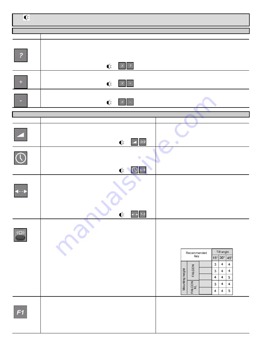
REJECTION
MODE
Press the REJECTION MODE key (8).
Perturbations immunity is used to avoid detection due to environmental
perturbations (vibrations, rains, etc).
“Pedestrian/parallel traffic rejection” provides both rejection of pedestrian
and rejection of any parallel traffic simultaneously.
Use the NUMBER keys 1- 5 (1) to enter the required rejection mode :
Key 1 : detection of all kind of targets in motion
Key 2 : detection of all kind of targets in motion
+ perturbations immunity
Key 3 : Low “Pedestrian/parallel traffic” rejection
+ perturbations immunity
Key 4 : Mid “Pedestrian/parallel traffic” rejection
+ perturbations immunity
Key 5 : High “Pedestrian/parallel traffic” rejection
+ perturbations immunity
The discrimination between a pedestrian and the different
vehicles depends mainly on the mounting height and the
microwave module tilt angle. Be careful that the rejection
function increases the response time of the sensor.
Use the next table as suggestions and do not hesitate to
increase or decrease the rejection level to obtain the required
rejection.
OUTPUT
REDIRECTION
Press the OUTPUT REDIRECTION key (2) to switch from one mode to
another.
Key 0: regular operating mode (standard FALCON).
Key 1: pedestrian or vehicle mode detection
Any motion detected activates relay 1.
Motion of vehicle triggers relay 2.
Pedestrian or vehicle mode detection only works if pedestrian
rejection is enabled (immunity parameter set to 3,4 or 5).
Otherwise the sensor does not classify target types and as a
consequence is never able to trigger relay 2.
23 ft
16.5 ft
11.5 ft
10 ft
7.5 ft


