BEA Br3 User Manual Download Page 9

The MC29 function provides a sequence for Relay 1 and/or Relay 

2 triggered by Input 1 or ‘WET’ Input.  Additionally Input 2 provides 

a door position switch input which allows the Relay 1 to deactivate 

once Input 2 is opened after the sequence has run.   Input 2 also 

allows the delay to run when Input 2 is opened, but not run when 

closed, as in the MC28.  Input 3 provides an input to disable the 

sequence whose logic is also selectable.   Simply put Relay 1 will 

be active the entire time until the normally opened door position 

switch signifies that the door has come closed again.   

Adjustable 

parameters include 

H1

 for activation hold time of Relay 1 after the 

door position switch has closed, 

H2

 for activation hold time of Relay 

2, 

D1

 for delay between activation of Relay 1 to Relay 2 and 

RL

 for 

reverse logic for Input 3.

NOTE

:  The delay timer will only fire one time during initial activation 

or maintained input.

NOTE:  The door position switch must have an opened contact 

when the door is closed, and a closed contact when it is not. 

(Position switch logic is different than 21, 22, 50 and 55.) 

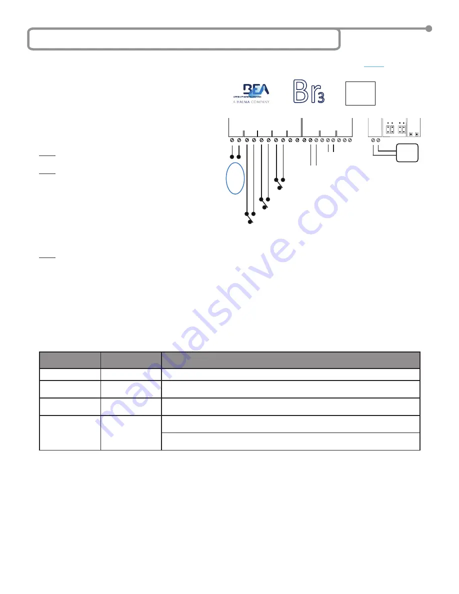
A typical application is a security door in which you have a push-

plate to start the sequence to unlock the Maglock, which you would 

want unlocked for the entire sequence until the door becomes 

closed again, then activate the door controller and an additional 

door position switch.  For this scenario the push-plate would be 

wired to Input 1, the position switch would be wired to Input 2,  the 

Maglock would be wired to Relay 1 and the door controller would 

be wired to Relay 2.  An example wiring diagram for this scenario is 

shown.

NOTE:   While the ‘WET’ Input is not involved in our typical 

application, it will still function as Input 1 does if used.

MC29 SETUP

1.  Wire the Br3 accordingly.

2.  Select the MC29 as the function according to the steps outlined in Section 5 – Selecting the Function.

•  Press and hold both push buttons (INCR & PARAM) for three (3) seconds to activate the display.

•  Press the INCR button to toggle through each function and select 

29

.

3.  Set the MC29 parameters according to the steps outlined in Section 5 – Selecting the Function.  

•  Press PARAM button to cycle through and set the parameters.

•  Press the INCR button to increment the parameter’s value.

Parameters for the MC29 function are shown in the chart.  Set the parameters as needed for the application, and wait for the display to 

become inactive to save the configuration.

PARAMETER

(PARAM Button)

DESCRIPTION

POSSIBLE VALUES

     (INCR Button)

H1

Relay 1 hold time

00

’ through ‘

60

’ - Relay 1 hold time will not begin counting down until the release of Input 2.

H2

Relay 2 hold time

00

’ through ‘

60

’ - Relay 2 hold time will not begin counting down until the delay between 

Relay 1 and Relay 2 expires.

D1

Delay between 

Relay 1 and Relay 2

00

’, ‘_

1

’ (1/4), ‘_

2

’ (1/2), ‘_

3

’ (3/4), ‘

01

’ through ‘

60

’ seconds. The delay time will begin counting 

down with the activation of the sequence.

RL

Input 3 Logic

00

’ = Normal Logic:  The activation device at Input 3 must be normally opened

                                   and close it’s contacts to disable the sequence.

01

’ = Reverse Logic:  The activation device at Input 3 must be normally 

                                    closed and open it’s contacts to disable the sequence.

4.  Once programming is complete, test the Br3.   Trigger the sequence via Input 1 or ‘WET’ Input.  Ensure that the sequence runs and the 

relays activate and the timers are as programmed.  The display will show 

R1

 when Relay 1 is energized, 

R2

 when Relay 2 is energized and 

R=

 when both Relay 1 and Relay 2 are energized at the same time.  Ensure that the delay between Relay 1 and Relay 2 runs when the 

sequence starts from the door closed position.  Ensure that Relay 1 stays active the entire time until the door returns to the closed position. 

Now, re-run the sequence; however this time before the door reaches the closed position, reactivate the door and ensure that the door 

reactivates immediately as the delay between timer, 

D1

 does NOT run.  Finally check the sequence disabling feature by triggering Input 3, 

while at the same time attempting to run the sequence by triggering Input 1 or ‘WET’ Input.  The sequence should NOT run again until Input 

3 is released.

5.  Upon completion of the above steps, walk test the door to ensure all functions, timers, sensors, etc. are working as intended and that the 

system is in compliance with all applicable standards (i.e. ANSI A156.10, A156.19). 

6G   Function 

29

 - Relay 1 Deactivation Timer (MC29)

Page 9 of 15 


75.5501.02  EN   20091102   (75.5500)

G

N

D

IN

-1

G

N

D

IN

-2

G

N

D

IN

-3

G

N

D

IN

-4

1

2

3

4

WET

WET

WET

N

C

N

O

C

O

M

N

C

N

O

C

O

M

12

-2

4V

AC

/D

C

RELAYS

1

2

POWER

RELAY 1

IN

C

R

.

PARAM

SETUP

D

C

AC

D

R

Y

W

ET

INPUTS

2 9

N

C

N

O

C

O

M

3

Br

3

CAUTION:  RELAY 1 WET 

OUTPUT OPTION 

IS ACTIVE FOR 

ALL FUNCTIONS.

12 to 24

 VAC/VDC

+/- 10%

To Activation Circuit 

of Door Control.

Pushplate or other 

Dry Contact Device.

‘WET’ 

12 to 24

 VAC/VDC

+/- 10%

INPUT

+      -

Typically Connected to Lock Device.  When DC ‘WET’

Output is Selected for Relay 1, COM Terminal is Positive (+).

Input 2 is for the Door Position Switch.

Switch is open when door is closed.

Fire Alarm Input

Disables normal operation.

NOTE: Input logic is selectible by ( 

R L 

)


Reverse Logic.

Summary of Contents for Br3

Page 1: ...n switch input for which closing it will re inhibit Input 1 Simply put this function is a combination between a LE21 and MC25 6 2 5 MC25 2 Relay Sequence Provides a sequence for Relay 1 and or Relay 2 triggered by Input 1 or WET Input 7 2 8 MC28 2 Relay Sequence w Door Position Input Provides a sequence for Relay 1 and or Relay 2 triggered by Input 1 or WET Input Additionally Input 2 provides a do...

Page 2: ...IPTION SPECIFICATION Supply Voltage 12 to 24 VAC VDC 10 Contact Rating DRY Relay 1 Relay 2 Relay 3 Contact Rating WET Relay 1 3 A at 24 VAC 3 A at 30 VDC 3 A at 24 VAC 3 A at 30 VDC 1 A at 24 VAC 1 A at 30 VDC 1 A Current Consumption 30 to 130 mA DRY Output Temperature Range 15 F 26 C to 150 F 65 C Dimensions 5 2 133mm W x 2 2 55mm D x 1 25mm H Input Specification Inputs 1 to 4 DRY Contact WET Inp...

Page 3: ...long as no relays are active the display will show the function selected otherwise it will show those relays Once the values are changed they are only saved after the display goes inactive again 5 seconds NOTE Remember that the INCR push button always increments the value of the parameter that you are looking at and the PARAM push button toggles through the available parameters NOTE To change only...

Page 4: ...system is in compliance with all applicable standards i e ANSI A156 10 A156 19 75 5501 02 EN 20091102 75 5500 Page 4 of 15 6A Function 10 Timer Module MC10 GND IN 1 GND IN 2 GND IN 3 GND IN 4 1 2 3 4 WET WET WET NC NO COM NC NO COM 12 24V AC DC RELAYS 1 2 POWER RELAY 1 INCR PARAM SETUP DC AC DRY WET INPUTS 1 0 NC NO COM 3 Br3 CAUTION RELAY 1 WET OUTPUT OPTION IS ACTIVE FOR ALL FUNCTIONS 12 to 24 V...

Page 5: ...le parameter for the LE21 function is shown in the chart Set it as needed for the application and wait for the display to become inactive to save the configuration PARAMETER PARAM Button DESCRIPTION POSSIBLE VALUES INCR Button H1 Relay 1 hold time 00 through 60 Relay 1 hold time will not begin counting down until the release of an activation input 4 Once programming is complete test the Br3 Attemp...

Page 6: ...M button to cycle through and set the parameters Press the INCR button to increment the parameter s value Parameters for the LE22 function are shown in the chart Set the parameters as needed for the application and wait for the display to become inactive to save the configuration PARAMETER PARAM Button DESCRIPTION POSSIBLE VALUES INCR Button H1 Relay 1 hold time 00 through 60 Relay 1 hold time wil...

Page 7: ...ding to the steps outlined in Section 5 Selecting the Function Press PARAM button to cycle through and set the parameters Press the INCR button to increment the parameter s value Parameters for the MC25 function are shown in the chart Set the parameters as needed for the application and wait for the display to become inactive to save the configuration PARAMETER PARAM Button DESCRIPTION POSSIBLE VA...

Page 8: ...ers Press the INCR button to increment the parameter s value Parameters for the MC28 function are shown in the chart Set the parameters as needed for the application and wait for the display to become inactive to save the configuration PARAMETER PARAM Button DESCRIPTION POSSIBLE VALUES INCR Button H1 Relay 1 hold time 00 through 60 Relay 1 hold time will not begin counting down until the release o...

Page 9: ...METER PARAM Button DESCRIPTION POSSIBLE VALUES INCR Button H1 Relay 1 hold time 00 through 60 Relay 1 hold time will not begin counting down until the release of Input 2 H2 Relay 2 hold time 00 through 60 Relay 2 hold time will not begin counting down until the delay between Relay 1 and Relay 2 expires D1 Delay between Relay 1 and Relay 2 00 _1 1 4 _2 1 2 _3 3 4 01 through 60 seconds The delay tim...

Page 10: ... application it will still function as Input 1 does if used MC35 SETUP 1 Wire the Br3 accordingly 2 Select the MC35 as the function according to the steps outlined in Section 5 Selecting the Function Press and hold both push buttons INCR PARAM for three 3 seconds to activate the display Press the INCR button to toggle through each function and select 35 3 Set the MC35 parameters according to the s...

Page 11: ...ay to become inactive to save the configuration PARAMETER PARAM Button DESCRIPTION POSSIBLE VALUES INCR Button H1 Relay 1 hold time 00 through 60 Relay 1 hold time will not begin counting down until the release of Input 1 H2 Relay 2 hold time 00 through 60 Relay 2 hold time will not begin counting down until the release of Input 2 4 Once programming is complete test the Br3 Wait until both doors a...

Page 12: ...set for the MC55 as the state of Relay 1 and Relay 2 are not based on time so just wait for the display to become inactive to save the configuration 4 Once programming is complete test the Br3 Wait until both doors are closed then trigger Relay 1 via Input 1 Ensure that Relay 1 changes state and that is maintained The display will show R1 when Relay 1 is energized Test the interlock by attempting ...

Page 13: ...n to increment the parameter s value Parameters for the MC65 function are shown in the chart Set the parameters as needed for the application and wait for the display to become inactive to save the configuration PARAMETER PARAM Button DESCRIPTION POSSIBLE VALUES INCR Button H1 Relay 1 hold time 00 through 60 Relay 1 hold time will not begin counting down until the release of Input 1 for inbound or...

Page 14: ...e Function Press PARAM button to cycle through and set the parameters Press the INCR button to increment the parameter s value Parameters for the MC75 function are shown in the chart Set the parameters as needed for the application and wait for the display to become inactive to save the configuration PARAMETER PARAM Button DESCRIPTION POSSIBLE VALUES INCR Button H1 Relay 1 hold time 00 through 60 ...

Page 15: ...programmed 3 Jumper an active Input and ensure that the fault is not within the wiring If module works when jumped trace wiring from Inputs relays 4 Replace module Module reacts to input but has no output 1 Wrong outputs are connected 2 Incorrect wiring 3 Incorrect jumper settings 4 Faulty module 1 Check to ensure that the proper outputs are connected per the function selected 2 Trace all wiring t...

Reviews: