BEA Br3 User Manual Download Page 2

Page 2 of 15 


75.5501.02  EN   20091102   (75.5500)

2   Specifications

3   Precautions

Shut off all power before attempting any wiring procedures.

Maintain a clean & safe environment when working in public areas.

Constantly be aware of pedestrian traffic around the door area.

Always stop pedestrian traffic through the doorway when performing tests that may result in unexpected reactions by the door.

ESD: Circuit boards are vulnerable to damage by electrostatic discharge. Before handling ensure you dissipate your body’s 

charge.

Always check placement of components before powering up so that moving parts will not catch any wires or cause damage to 

equipment.

Ensure compliance with all applicable safety standards (i.e. ANSI A156.10 / 19) upon completion of installation.

When preparing to wire multiple devices together for a ‘system’ configuration, it is best to ensure the correct operation of each 

device independently before starting to help reduce troubleshooting time later, in the event of a discrepancy.

When applying equipment on a new installation, utilizing new electrical supply circuits, always ensure that correct line voltage 

exists and is stable.  Remember to shut the power back off once this is checked, before performing any wiring to the system.

DO NOT attempt any internal repair of the sensor. All repairs and/or component replacements must be performed by BEA, Inc. 

Unauthorized disassembly or repair:

1.  May jeopardize personal safety and may expose one to the risk of electrical shock.

2.  May adversely affect the safe and reliable performance of the product resulting in a voided warranty.

*

NOTE: If the Br3 is powered with AC voltage and is using the ‘WET” output to convert to DC, and the current draw of the device is greater 

than .9 amps the upper temperature range is +130°F (54°C).

DESCRIPTION

SPECIFICATION

DESCRIPTION

SPECIFICATION

Supply Voltage

12 to 24 VAC/VDC: +/- 10%

Contact Rating ‘DRY’ - Relay 1

- Relay 2

 - Relay 3 

Contact Rating ‘WET’ - Relay 1

3 A at 24 VAC; 3 A at 30 VDC

3 A at 24 VAC; 3 A at 30 VDC

1 A at 24 VAC; 1 A at 30 VDC

1 A

Current Consumption 30 to 130 mA (‘DRY’ Output)

Temperature Range

-15°F (-26°C) to +150°F (65°C)

*

Dimensions

5.2” (133mm) W x 2.2” (55mm) D x 1” (25mm) H

Input Specification

Inputs 1 to 4: ‘DRY’ Contact

‘WET’ Input:

5 VAC/VDC to 24 VAC/VDC: +/- 10%

Housing Material

ABS – Grey Translucent
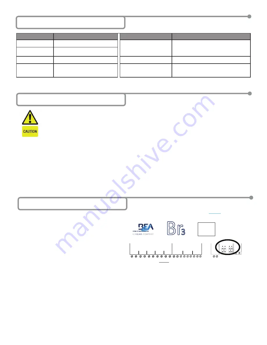
4   Jumper Settings

1.

The Br3 contains two (2) sets of jumpers.  Both sets deal 

with configuring Relay 1 options:
Jumper set 1 configures whether or not to output AC or 

DC voltage if the ‘WET’ output is selected.  Jumper set 2 

configures whether or not the Relay 1 output is ‘WET’ or 

‘DRY’.  The ‘WET’ voltage output means that the module 

will supply a voltage output of up to 1 Amp on Relay 

1 to power electric strikes and magnetic locks without 

the need for an external power supply. This feature can 

greatly simplify the installation (as long as the power 

supply powering the Br3 is rated for 1 Amp).

The ‘WET’ output can also be set using jumpers to output 

DC if the Br3 is supplied with AC, otherwise it will just 

pass the AC voltage that is supplied. Similarly if powered 

by DC, the ‘WET’ output will only output DC.

•   To set Relay 1 to output DC (if ‘WET’) move 

both

 shunts (2) on Jumper Set 1, to the two (2) lower pins.

•   To set Relay 1 to output AC (if ‘WET’ and powered with AC) move 

both

 shunts (2) on Jumper Set 1, to the two (2) upper pins.

•   To set Relay 1 to output ‘DRY’ (Jumper Set 1 becomes unused), move 

both

 shunts (2) on Jumper Set 2, to the two (2) lower pins.

•   To set Relay 1 to output ‘WET’, move 

both

 shunts (2) on Jumper Set 2, to the two (2) upper pins.

G

N

D

IN

-1

G

N

D

IN

-2

G

N

D

IN

-3

G

N

D

IN

-4

1

2

3

4

WET

WET

WET

N

C

N

O

C

O

M

N

C

N

O

C

O

M

12

-2

4V

AC

/D

C

RELAYS

1

2

POWER

RELAY 1

IN

C

R

.

PARAM

SETUP

D

C

AC

D

R

Y

W

ET

INPUTS

00

N

C

N

O

C

O

M

3

Br

3

CAUTION:  RELAY 1 WET 

OUTPUT OPTION 

IS ACTIVE FOR 

ALL FUNCTIONS.

NOTE: Default jumper settings make Relay 1 output 

‘DRY’ only. All four jumpers set to lower pins.

Summary of Contents for Br3

Page 1: ...n switch input for which closing it will re inhibit Input 1 Simply put this function is a combination between a LE21 and MC25 6 2 5 MC25 2 Relay Sequence Provides a sequence for Relay 1 and or Relay 2 triggered by Input 1 or WET Input 7 2 8 MC28 2 Relay Sequence w Door Position Input Provides a sequence for Relay 1 and or Relay 2 triggered by Input 1 or WET Input Additionally Input 2 provides a do...

Page 2: ...IPTION SPECIFICATION Supply Voltage 12 to 24 VAC VDC 10 Contact Rating DRY Relay 1 Relay 2 Relay 3 Contact Rating WET Relay 1 3 A at 24 VAC 3 A at 30 VDC 3 A at 24 VAC 3 A at 30 VDC 1 A at 24 VAC 1 A at 30 VDC 1 A Current Consumption 30 to 130 mA DRY Output Temperature Range 15 F 26 C to 150 F 65 C Dimensions 5 2 133mm W x 2 2 55mm D x 1 25mm H Input Specification Inputs 1 to 4 DRY Contact WET Inp...

Page 3: ...long as no relays are active the display will show the function selected otherwise it will show those relays Once the values are changed they are only saved after the display goes inactive again 5 seconds NOTE Remember that the INCR push button always increments the value of the parameter that you are looking at and the PARAM push button toggles through the available parameters NOTE To change only...

Page 4: ...system is in compliance with all applicable standards i e ANSI A156 10 A156 19 75 5501 02 EN 20091102 75 5500 Page 4 of 15 6A Function 10 Timer Module MC10 GND IN 1 GND IN 2 GND IN 3 GND IN 4 1 2 3 4 WET WET WET NC NO COM NC NO COM 12 24V AC DC RELAYS 1 2 POWER RELAY 1 INCR PARAM SETUP DC AC DRY WET INPUTS 1 0 NC NO COM 3 Br3 CAUTION RELAY 1 WET OUTPUT OPTION IS ACTIVE FOR ALL FUNCTIONS 12 to 24 V...

Page 5: ...le parameter for the LE21 function is shown in the chart Set it as needed for the application and wait for the display to become inactive to save the configuration PARAMETER PARAM Button DESCRIPTION POSSIBLE VALUES INCR Button H1 Relay 1 hold time 00 through 60 Relay 1 hold time will not begin counting down until the release of an activation input 4 Once programming is complete test the Br3 Attemp...

Page 6: ...M button to cycle through and set the parameters Press the INCR button to increment the parameter s value Parameters for the LE22 function are shown in the chart Set the parameters as needed for the application and wait for the display to become inactive to save the configuration PARAMETER PARAM Button DESCRIPTION POSSIBLE VALUES INCR Button H1 Relay 1 hold time 00 through 60 Relay 1 hold time wil...

Page 7: ...ding to the steps outlined in Section 5 Selecting the Function Press PARAM button to cycle through and set the parameters Press the INCR button to increment the parameter s value Parameters for the MC25 function are shown in the chart Set the parameters as needed for the application and wait for the display to become inactive to save the configuration PARAMETER PARAM Button DESCRIPTION POSSIBLE VA...

Page 8: ...ers Press the INCR button to increment the parameter s value Parameters for the MC28 function are shown in the chart Set the parameters as needed for the application and wait for the display to become inactive to save the configuration PARAMETER PARAM Button DESCRIPTION POSSIBLE VALUES INCR Button H1 Relay 1 hold time 00 through 60 Relay 1 hold time will not begin counting down until the release o...

Page 9: ...METER PARAM Button DESCRIPTION POSSIBLE VALUES INCR Button H1 Relay 1 hold time 00 through 60 Relay 1 hold time will not begin counting down until the release of Input 2 H2 Relay 2 hold time 00 through 60 Relay 2 hold time will not begin counting down until the delay between Relay 1 and Relay 2 expires D1 Delay between Relay 1 and Relay 2 00 _1 1 4 _2 1 2 _3 3 4 01 through 60 seconds The delay tim...

Page 10: ... application it will still function as Input 1 does if used MC35 SETUP 1 Wire the Br3 accordingly 2 Select the MC35 as the function according to the steps outlined in Section 5 Selecting the Function Press and hold both push buttons INCR PARAM for three 3 seconds to activate the display Press the INCR button to toggle through each function and select 35 3 Set the MC35 parameters according to the s...

Page 11: ...ay to become inactive to save the configuration PARAMETER PARAM Button DESCRIPTION POSSIBLE VALUES INCR Button H1 Relay 1 hold time 00 through 60 Relay 1 hold time will not begin counting down until the release of Input 1 H2 Relay 2 hold time 00 through 60 Relay 2 hold time will not begin counting down until the release of Input 2 4 Once programming is complete test the Br3 Wait until both doors a...

Page 12: ...set for the MC55 as the state of Relay 1 and Relay 2 are not based on time so just wait for the display to become inactive to save the configuration 4 Once programming is complete test the Br3 Wait until both doors are closed then trigger Relay 1 via Input 1 Ensure that Relay 1 changes state and that is maintained The display will show R1 when Relay 1 is energized Test the interlock by attempting ...

Page 13: ...n to increment the parameter s value Parameters for the MC65 function are shown in the chart Set the parameters as needed for the application and wait for the display to become inactive to save the configuration PARAMETER PARAM Button DESCRIPTION POSSIBLE VALUES INCR Button H1 Relay 1 hold time 00 through 60 Relay 1 hold time will not begin counting down until the release of Input 1 for inbound or...

Page 14: ...e Function Press PARAM button to cycle through and set the parameters Press the INCR button to increment the parameter s value Parameters for the MC75 function are shown in the chart Set the parameters as needed for the application and wait for the display to become inactive to save the configuration PARAMETER PARAM Button DESCRIPTION POSSIBLE VALUES INCR Button H1 Relay 1 hold time 00 through 60 ...

Page 15: ...programmed 3 Jumper an active Input and ensure that the fault is not within the wiring If module works when jumped trace wiring from Inputs relays 4 Replace module Module reacts to input but has no output 1 Wrong outputs are connected 2 Incorrect wiring 3 Incorrect jumper settings 4 Faulty module 1 Check to ensure that the proper outputs are connected per the function selected 2 Trace all wiring t...

Reviews: