


Page
12
of
16
75.5652.01
20100830
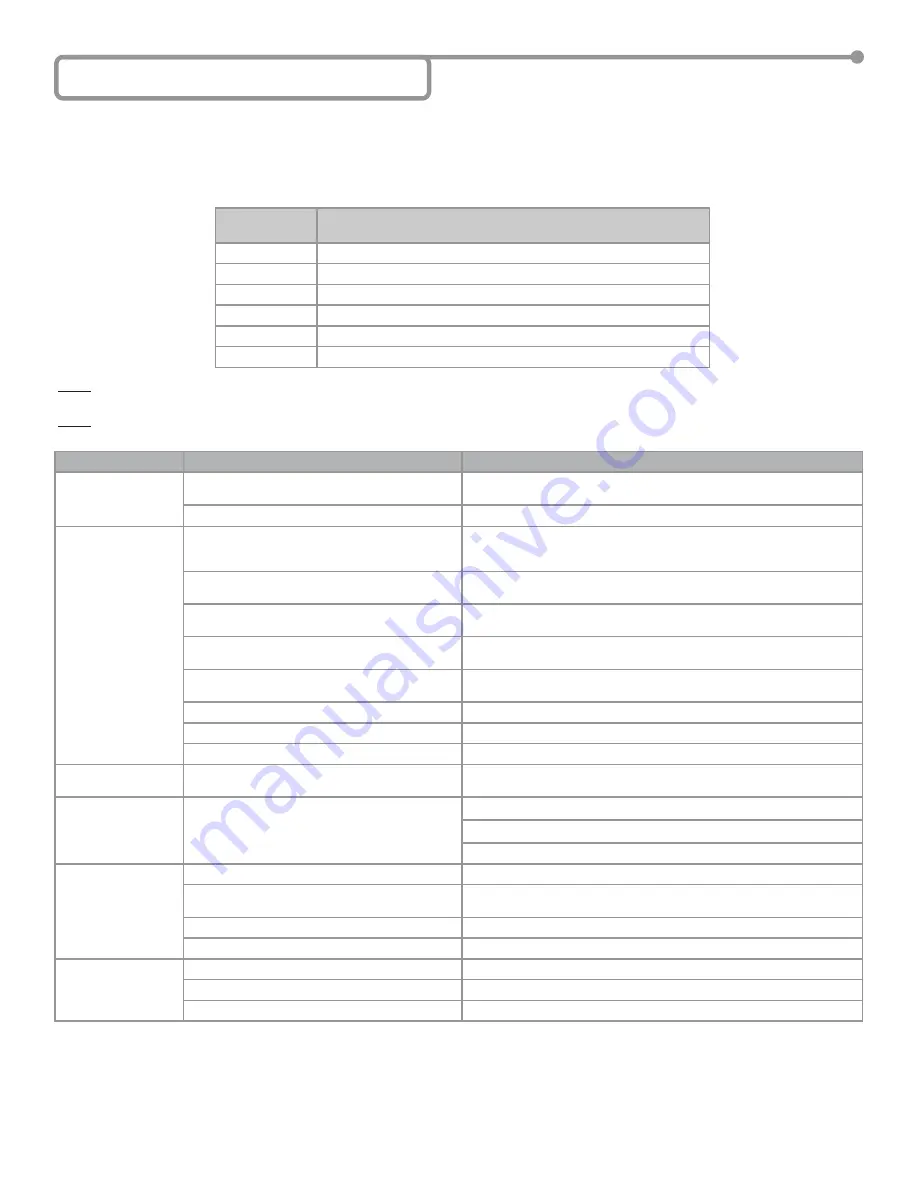
8 Troubleshooting
PROBLEM
PROBABLE CAUSE
CORRECTIVE ACTION
DP-Hub is not
showing any display
No input power
Check input power as it must be 12 to 24 VAC/VDC: +/- 10%,
do not
power from the door control
Faulty DP-Hub
Replace DP-Hub
Door will not open or
close
Door control issue
Remove the DP-Hub from the door control by unplugging the Door
Control Harness(es). Attempt to open the door via the door control. If
door does NOT open, troubleshoot door control
No inputs or outputs connected
Connect (as a minimum) the ON/OFF/HOLD Switch in the ON position,
the BodyGuard, the EDPS(s), an activation device and door control
BodyGuard data and/or relay con
fi
guration and/or
pattern width is incorrect
Verify BodyGuard relay con
fi
guration, BodyGuard data type matches
DP-Hub and pattern width is set correctly
DP-Hub function
FA
set to
01
when no AUX is
used
Check function
FA
at the hub. If no AUX device is used, value should be
set to
00
Safety Beam input
Fb
is set incorrectly
Check function
Fb
at the hub. If no SBK-30 beams are plugged into the
hub, value should be set to
00
SBK-30 Beams misaligned
Align SBK-30 Beams
SBK-30 Beams faulty
Replace SBK-30 Beams
Door Mounted Sensor wiring is incorrect
Check wiring of Door Mounted Sensors (Section 5-6)
Door keeps recycling
open (ghosting).
Activation sensor ‘seeing’ the door movement.
Adjust motion sensor or door mounted sensor at non-safety side.
BodyGuard
fl
ashing
orange
Bodyguard data is incorrect
Check and change F1 at BodyGuard if needed
Check and change
FL
at DP-Hub if needed
Check wiring of BodyGuard (Section 5-4)
Error codes
E1
&
E3
EDPS is not connected to DP-Hub
Check wiring of EDPS (Section 5-7)
EDPS is con
fi
gured for 2 doors but is installed on
a 1 door system
Check function
Fd
at the hub. If it only a 1 door system, value should be
set to
01
Faulty EDPS
Replace EDPS
Faulty DP-Hub
Replace DP-Hub
Error codes
E2
&
E4
EDPS is not connected correctly to DP-Hub
Check wiring of EDPS (Section 5-7)
Faulty EDPS
Replace EDPS
Faulty DP-Hub
Replace DP-Hub
If the DP-Hub is powered on and acting erratically, the best solution is to
fi
rst use the ‘Operating Parameters’ in conjunction with the
‘Programming Parameters” as described in Section 6 - Programming the DP-Hub for troubleshooting. The information obtained can also be
used with the six LEDs on the DP-Hub. The description of the LEDs is shown below. Once the problem is determined the
corrective actions can be taken as speci
fi
ed by the second table. Finally if you cannot solve the problem on your own, you can contact BEA
Technical Support whose contact information is provided in Section 9.
LED
DESCRIPTION
Green
DP-Hub activation relay is active
Yellow
DP-Hub stall relay is active
Red
DP-Hub safety relay is active
Orange
DP-Hub home switch is active (contact is closed)
Blue
DP-Hub is in Learn mode
White
EDPS baseline is being tracked
NOTE: If the display goes blank but you have HOME, LEARN and TRACKING, the DP-Hub is relearning the sensor baseline for approximately one
second - this is normal.
NOTE: When troubleshooting with error codes, the lower error code number is a higher priority error. Fixing the lowest error code number
fi
rst may
resolve subsequent errors.