background image

30

Invert Electrode Signal (Mode 0)

The action of the signal is inverted.

Default Switch Back Time (Modes 1, 2, 3, 4 & 5)

The time, in seconds, in which the hand will revert back from 

the alternate to the default grip pattern.

Note: A zero disables the parameter.

Grip Switch Time (Modes 1, 2, 3, & 4)

The time, in seconds, in which the user can switch between 

the alternate grip patterns and the default grip patterns (and 

vice-versa).

Open Dwell Time (Mode 1)

The maximum time in milliseconds the control signal has to 

be asserted before being recognised as an Open signal.

5.5.10 be Button Bar

The  buttons  on  the  top  of  the  ‘bebionic  main’  window, 

enables Load, Save, Read & Update Hand Configurations 

as required.

Restore Defaults

To  restart  configuration,  clicking  the  ‘Restore  Defaults’ 

button reverts all the controls to the default settings for the 

current mode.

Save

The hand configuration can be stored by clicking the ‘Save’ 

button.  Before  data  is  saved,  a  patient  name  or  identifier 

must be entered. There is a description field for recording 

specific information as necessary. 

Clicking  the  ‘Save  Record’  button  will  trigger  a  prompt, 

asking if the settings are correct. 

Once  a  configuration  is  saved,  the  time  and  date  is  also 

saved automatically as shown below. 

Auto Grip (Modes 4 & 5)

The Auto Grip functions in Tripod grip only and is activated 

by providing three consecutive close signals. Deactivation 

occurs when the hand is given an Open signal.

If movement / slippage of an object is detected, the finger 

position  /  grip  force  is  automatically  altered  to  provide  a 

more secure grip.

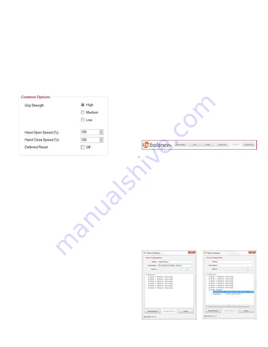
Speed Control (All Modes)

This  option  is  the  adjustable  maximum  speed  for  both 

open  and  close.  The  numeric  up/down  controls  provide 

independent  hand  opening  and  closing  speeds;  100% 

(default) being the maximum.

Deferred Reset (All Modes)

When enabled, each time the hand resets, the automated 

calibration sequence is paused until the user gives an open 

signal. 

This  feature  has  been  added  for  patients  using  elbow 

systems  and  prevents  held  objects  from  being  dropped 

when the elbow power is cycled.

Close Dwell Time (Mode 1)

The minimum time in milliseconds the control signal has to 

be asserted before being recognised as a Close signal.

Direction Change Time (Mode 3)

The  time,  in  milliseconds,  in  which  an  applied  signal  will 

repeat the last action. 

Grip Strength (All Modes)

It  is  possible  to  either  select  High,  Medium  or  Low  grip 

strength. This setting provides adjustment of the grip strength 

and battery consumption; if a lower setting is selected, this 

will result in a lower grip strength and a prolonged battery 

life.

Note: This has minimal effect on operation speed.

5.5.9 Advanced Options 

In be, adjustment of further specific features can 

be accessed by clicking on ‘Advanced’, which will open 

a dialog box. The features displayed will be appropriate 

to the mode selected, and are detailed in the following 

sections. 

Summary of Contents for BBHLG

Page 1: ...1 Technical Manual BBHMD BBHLG...

Page 2: ...2...

Page 3: ...ng the bebionic glove 4 0 Connections Compatibility 17 21 4 1 Wrist Options 4 2 Battery Options 4 3 Power Information 4 4 System Connections 4 5 System Compatibility 5 0 bebalance 23 31 5 1 Introducti...

Page 4: ...ability of the product and could impact product warranty WARNING We do not recommend the use of carbon fibre materials in fabricating a prosthetic arm due to electrical conductivity If however it is u...

Page 5: ...e tripod grip 1 0 seconds maximum time to open or close power grip 0 5 seconds maximum time to open or close key grip 1 0 seconds maximum static load hook grip 99lb 3oz 45kg maximum load individual fi...

Page 6: ...of grip and speed Speed and grip force are set to maximum To alternate between the default and alternative grip pattern an OPEN OPEN signal must be applied i e the hand must be fully opened the signal...

Page 7: ...The assembly must be retightened before electrically driving the thumb A Program Switch is provided on the back of the hand This has four functions 1 Switch the hand ON and OFF A single press for app...

Page 8: ...until they meet resistance or the close signal stops This type of grip allows users to pick up hold and manipulate a variety of everyday objects such as car keys coins jar lids and pens Hook With the...

Page 9: ...The thumb moves to the midpoint of its range and pauses The Index is then active and under user control To achieve this grip it is necessary for the thumb to be manually repositioned by the practitio...

Page 10: ...ly close The thumb then closes onto the side of the index finger The thumb position may be raised and lowered without moving the other four fingers allowing for release capture or reposition of the ob...

Page 11: ...ddle and ring fingers providing stability The index finger closes on to the mouse button and then backs off to provide the button press Each close signal will give a mouse click whilst an open signal...

Page 12: ...12...

Page 13: ...e has been designed specifically for use with the bebionic hand The use of other gloves may damage the hand and will void the warranty CAUTION 3 0 bebionic Glove Care Take care when fitting and using...

Page 14: ...he hand is in glove donning mode CAUTION Do not use talcum powder or lubricant when fitting the glove CAUTION 3 4 Press and hold the program switch for six seconds The hand will automatically drive in...

Page 15: ...ressing the program switch for approximately three seconds Next put the hand into glove donning mode by pressing the program switch for 4 seconds Roll up the base of the glove and pull the whole glove...

Page 16: ...16...

Page 17: ...y the patient Multi Flex Wrist The Flexion Wrist from Motion Control is a simple flexion device that allows the wearer to easily lock or unlock the wrist position and reposition the wrist in either a...

Page 18: ...tery and requires an additional connector cable to link to the hand The connector cable for EQD hands as shown on page 19 is supplied with each battery For short wrist or friction wrist options a diff...

Page 19: ...nts not to scale The system detailed below is suitable for a bebionic hand with an Electronic Quick Disconnect Multi Flex and Flex Wrist BBI 2200S bebionic 7 4V 2200mAh split or single cell battery B2...

Page 20: ...rdered separately for hands with Short Wrist Components not to scale The system detailed below is suitable for a bebionic hand with a Short Wrist 13E190 150 connector BBI 2200S bebionic 7 4V 2200mAh s...

Page 21: ...Otto Bock 9X50 9X52 Linear Transducer Supplier Part Number Name Otto Bock 12K44 ErgoArm Hybrid Plus Otto Bock 12K50 ErgoArm Electronic Plus Otto Bock 12K100N DynamicArm Otto Bock 12K110N DynamicArm Pl...

Page 22: ...22...

Page 23: ...ful if muscles produce limited or difficult to control signals as is often the case with higher level amputation With bebalance the practitioner may adjust the operation of the electrode reset co cont...

Page 24: ...need to be un installed as this will run separately from bebalance Note Only one version of the bebalance software can run at any one time The bebalance software requires the Net Framework 4 0 to oper...

Page 25: ...e medium large hands use either a red or black RF Dongle 4 2 1 3 5 4 Communications 5 4 1 Introduction To configure any bebionic hand for patient use the communications must first be enabled between t...

Page 26: ...tly transmitting this button will show as stop scanning once device scanning is in progress If no devices are being listed then make sure that the bebionic hand has the communications turned on This c...

Page 27: ...the user s ability to use their muscles to produce the required signals The number of electrodes used has an effect on which operating modes can be used The following clarifies this Dual Site Electrod...

Page 28: ...the relevant tables Proportional Control The speed and strength of the hand is proportional to the electrode signal produced by the user Threshold Control The speed and strength of the hand is consta...

Page 29: ...Back Time Grip Switch Time Direction Change Time Proportional Threshold Thumb Position Change Palm Switch Open Open Signal Mode 4 Open Open Signals Dual Site Electrode 2 x Transducers Open Apply sign...

Page 30: ...three consecutive close signals Deactivation occurs when the hand is given an Open signal If movement slippage of an object is detected the finger position grip force is automatically altered to prov...

Page 31: ...settings Communications This button gives us access to the communications form for connecting to all hands for both Bluetooth and RF USB dongles When a connection is made the communications status bo...

Page 32: ...be used to do so No key is required to disable this feature 5 7 Electrodes To monitor review and adjust the electrode signals select the Electrode Screen button to view the Myo Configuration Trainer w...

Page 33: ...t reaches the right hand side of the display click Stop The trace period can be changed by selecting the 10 20 or 30 seconds from the Display Period drop down menu The black horizontal lines identify...

Page 34: ...34...

Page 35: ...nty Re turns and Repairs 6 1 Repairs 1 2 The clevis link has been designed to bend should the hand be excessively loaded during use If this should occur the part will need to be replaced so that the f...

Page 36: ...t pin sits flush with the surface on both sides of the leadscrew 7 8 Ensure that the finger flexes fully forward and springs back to the upright position as shown in the two images above Finished 3 4...

Page 37: ...5 6 1 2 Using the screwdriver with the 1 50mm hex bit con tained within the toolkit loosen the screws in the rear cover Note Do not completely remove Slide gaiter flaps out from under the rear cover...

Page 38: ...strap is under the thumb Pay special attention to the thumb cable position Ensure the thumb section of the gaiter is pushed all the way to the gap shown in the image above Pull the gaiter strap aroun...

Page 39: ...ed Carefully push the flap all the way home under the rear cover Ensure there is as small a gap as possible between the gaiter and the rear cover Retighten both of the screws in the rear cover Note Do...

Page 40: ...ored by a programme of internal and external audits All individual products are marked indicating that they comply with the requirements of the Medical Devices Directive 93 42 EEC MDD The mark may be...

Page 41: ...y cause undesired operation of the device Under Industry Canada regulations this radio transmitter may only operate using an antenna of a type and maximum or lesser gain approved for the transmitter b...

Page 42: ...ulations this radio transmitter may only operate using an antenna of a type and maximum or lesser gain approved for the transmitter by Industry Canada To reduce potential radio interference to other u...

Page 43: ...lude details on date of purchase size medium or large and side left or right If bebionic components are to be returned for servicing please contact us or your local distributor stating the hand s seri...

Page 44: ...e a detrimental impact on health and the environment Please observe the instructions of your national authority pertaining to return and collection 6 7 Symbols Used Declaration of confirmity according...

Page 45: ...45...

Page 46: ...RSLLIT317 Issue 1 2017 www bebionic com Steeper Mayflower House 14 Pontefract Road Stourton LEEDS LS10 1TB Tel 44 0 870 240 4133 Email customerservices steepergroup com www steepergroup com...

Reviews: