background image

BDDF00160 Issue 1

10/40

Alaris™ GW Volumetric Pumps

Operating Precautions

Electromagnetic Compatibility and Interference

/

•  This Pump is protected against the effects of external interference, including high energy radio frequency 

emissions, magnetic fields and electrostatic discharge (for example, as generated by electrosurgical and 
cauterising equipment, large motors, portable radios, cellular telephones etc .) and is designed to remain safe 
when unreasonable levels of interference are encountered .

•  Therapeutic Radiation Equipment: Do not use the Pump in the vicinity of any Therapeutic Radiation 

Equipment . Levels of radiation generated by the radiation therapy equipment such as Linear Accelerator, 
may severely affect functioning of the Pump . Please consult manufacturer’s recommendations for safe 
distance and other precautionary requirements . For further information, please contact your local  BD 
representative .

MR

•  Magnetic Resonance Imaging (MRI): The Pump contains ferromagnetic materials which are susceptible 

to interference with magnetic field generated by the MRI devices . Therefore, the Pump is not considered 
an MRI compatible Pump as such . If use of the Pump within an MRI environment is unavoidable, then BD 
highly recommends securing the Pump at a safe distance from the magnetic field outside the identified 
Controlled Access Area in order to evade any magnetic interference to the Pump; or MRI image distortion . 
This safe distance should be established in accordance with the manufacturers’ recommendations regarding 
electromagnetic interference (EMI) . For further information, please refer to the product technical service 
manual (TSM) . Alternatively, contact your local BD representative for further guidance .

•  Accessories: Do not use any non-recommended accessory with the Pump . The Pump is tested and compliant 

with the relevant EMC claims only with the recommended accessories . Use of any accessory, transducer or 
cable other than those specified by BD may result in increased emissions or decreased Pump immunity .

&

•  In some circumstances the Pump may be affected by an electrostatic discharge through air at levels close 

to or above 15kv; or by radio frequency radiation close to or above 10v/m . If the Pump is affected by this 
external interference the Pump will remain in a safe mode; the Pump will duly stop the infusion and alert 
the user by generating a combination of visual and audible alarms . Should any encountered alarm condition 
persist even after user intervention, it is recommended to replace that particular Pump and quarantine the 
Pump for the attention of appropriately trained Qualified Service Personnel .

•  This Pump is a CISPR 11 Group 1 Class B device and uses RF energy only for its internal function in the normal 

product offering . Therefore, its RF emissions are very low and are not likely to cause any interference with the 
nearby electronic equipment . However, this Pump emits a certain level of electromagnetic radiation which 
is within the levels specified by IEC/EN60601-1-2 and IEC/EN60601-2-24 . If the Pump interacts with other 
equipment, measures should be taken to minimise the effects, for instance by repositioning or relocation .

•  For further information on electromagnetic compatibility, please consult Technical Service Manual, 

BDTM00006 .

Hazards

•  An explosion hazard exists if the Pump is used in the presence of flammable anaesthetics . Exercise care to 

locate the Pump away from any such hazardous sources . 

•  A fire hazard may exist if the Pump is used in the presence of high oxygen concentrations .

m

•  Dangerous Voltage: An electrical shock hazard exists if the Pump’s casing is opened or removed . Refer all 

servicing to Qualified Service Personnel .

V

•  Electrostatic discharge (ESD) precautions are required when connecting RS232/Nurse Call . Touching the pins 

of the connectors may result in ESD protection failure . It is recommended that all actions must be taken by 
appropriately Qualified Service Personnel .

*

•  If this Pump is dropped, subjected to excessive moisture, fluid spillage, humidity or high temperature, or 

otherwise suspected to have been damaged, remove it from service for inspection by Qualified Service 
Personnel . When transporting or storing the Pump, use original packaging where possible, and adhere to 
temperature, humidity and pressure ranges stated in the Specifications section and on the outer packaging .

•  Warning: Alaris GW 800 Volumetric Pumps should not be modified or altered in any way, except where 

explicitly directed or authorised by BD . Any use of Alaris GW 800 Volumetric Pumps which have been altered 
or modified otherwise than in strict application of directions provided by BD, is at your sole risk, and BD 
does not provide any warranty for or endorsement on any Alaris GW 800 Volumetric Pump that has been so 
modified or altered . BD product warranty shall not apply in the event the Alaris GW 800 Volumetric Pump 
has suffered damage or premature wear, or malfunctions or otherwise operates incorrectly, as a result of 
unauthorised modification or alteration of the Alaris GW 800 Volumetric Pump .

Summary of Contents for Alaris 800TIG2BGN1

Page 1: ...s Alaris GW 800 Volumetric Pump with Set Detection Mode disabled Directions For Use en ...

Page 2: ...Compatibility and Interference 10 Hazards 10 Getting Started 11 Initial Set Up 11 Power Input 11 Pole Clamp Installation 12 Docking Station Workstation or Equipment Rail Installation 12 Loading an Infusion Set 13 Power On Off 14 Battery Operation 14 Priming the Infusion Set 15 Automatic Set Detection 16 Starting the Infusion 17 Standard Mode 17 Standard Mode with VTBI Time Infusion on 17 Micro Mod...

Page 3: ...sion Sets 29 Standard Sets 29 Blood Sets 29 The Alaris Gateway Workstation 30 The Alaris DS Docking Station 30 Maintenance 31 Routine Maintenance Procedures 31 Battery Operation 31 Disposal 31 Cleaning and Storage 32 Cleaning the Pump 32 Storing the Pump 32 Cleaning and storing the Infusion set 32 Cleaning the Flow Sensor 32 Specifications 33 IrDA RS232 and Nurse Call Specification 36 RS232 IrDA F...

Page 4: ...ent however does BD make any representations or warranties concerning the adequacy and safe performance of any non dedicated infusion sets as it relates to the operation of the Pump and the accuracy of the infusion In no event shall BD be liable for any damages of any kind or nature including without limitation direct or indirect special consequential or incidental damages arising from or in conne...

Page 5: ...ections for Use and Technical Service Manual for your BD products These documents are referenced on bd com Paper copies of the Directions For Use can be obtained free of charge by contacting your local BD representative An estimated delivery time will be provided when the order is placed Conventions used in this manual BOLD Used for Display names software commands controls and indicators reference...

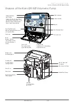
Page 6: ...on set Door Latch Press outer latch to open the Pump door Flow Stop Mechanism When activated the mechanism will stop fluid flow Flow Direction Label Bevel Releases the flow stop mechanism lever arm when the door is closed Keypad Display Indicators Air Sensor Pressure Sensor Mute Indicator Alarm Indicator Infra Red Communications port IrDA Folded Pole Clamp Potential Equalisation PE connector Mains...

Page 7: ...selected infusion configuration parameters Confirms the rate during an infusion titration hf CHEVRON keys Increases or decreases the infusion rate TIME limit and VTBI Press and hold to increase the selection speed Used to adjust user selectable options Indicators when illuminated Symbol Description S AC POWER indicator When illuminated the Pump is connected to an AC power supply RATE The Pump is d...

Page 8: ...ting Current s Device complies with the requirements of Council Directive 93 42 EEC as amended by 2007 47 EC T Date of Manufacture t Manufacturer Connector for Flow Sensor U Not for Municipal Waste W Fuse rating X Infusion indicator Displays fluid drops detected by the flow sensor when infusing in Standard mode Y Infusion indicator Displays fluid drops detected by the flow sensor when infusing in ...

Page 9: ...r clamp above the burette and open the clamp on the vent on top of the burette Discard Infusion set if the packaging is not intact or the protector cap is detached Ensure sets are not kinked as this may occlude the tubing BD recommends the use of the IVAC Model 180 Flow Sensor when using sets without anti siphon valves or the mandatory use of the IVAC Model 180 Flow Sensor whenever the Pump set de...

Page 10: ...l variation in pressures created within the local vascular system by such pumps Typical examples of those pumps are used during dialysis bypass or cardiac assist applications This Pump is suitable for use in Hospital and clinical environments other than domestic establishments and those directly connected to the public single phase AC mains power supply network that supplies buildings used for dom...

Page 11: ...ed alarm condition persist even after user intervention it is recommended to replace that particular Pump and quarantine the Pump for the attention of appropriately trained Qualified Service Personnel This Pump is a CISPR 11 Group 1 Class B device and uses RF energy only for its internal function in the normal product offering Therefore its RF emissions are very low and are not likely to cause any...

Page 12: ... adequate performance is not achieved then the Alaris GW 800 branded dedicated infusion sets should be used or the Pump should be recalibrated by following the volumetric calibration procedure described in the Technical Service Manual Addendum 1000SM00014 w Factory set calibration values in the Alaris GW 800 Volumetric Pump are intended specifically to support the use of Alaris GW 800 branded dedi...

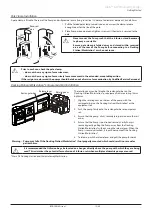
Page 13: ...uipment Rail Installation Release lever Rectangular bar Rotating cam The rotating cam can be fitted to the rectangular bar on the Docking Station Workstation or equipment rails measuring 10mm by 25mm 1 Align the rotating cam on the rear of the pump with the rectangular bar on the Docking Station Workstation or the equipment rail 2 Push the pump firmly onto the rectangular bar or equipment rail 3 E...

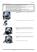
Page 14: ...73 303EV Infusion sets ensure a separation of at least 50cm is maintained between the Pump and the upper Back Check Valve 1 Close the in line clamp on the Infusion set Press the door latch to open the tubing cover door 2 Release the flow stop mechanism by pushing the lever arm up and to the right 3 Avoiding any slack insert the infusion set from left to right into the slot provided following the f...

Page 15: ...state w If the Pump alarms segments indicators do not light up correctly or 2 audible sounds are not heard then the Pump must be powered down immediately and Qualified Service Personnel contacted If transportation to an engineer is necessary it is recommended to use the original protective packaging Battery Operation The Pump will operate from the internal battery when AC Power is disconnected The...

Page 16: ...rom the set infusion rate occurs 1 Ensure the Pump is switched on and in line clamp is open 2 Load the Infusion set see Loading the Infusion Set 3 Press b button once E will be displayed 4 Press and hold b button while E is still displayed prime the Infusion set until there is no visible air in the IV line according to hospital protocol 5 Attach the set to the patient or other Infusion set 6 Start...

Page 17: ...utomatic set detection is set to On the Pump automatically tests that a compatible BD Infusion set has been loaded correctly refer to Compatible Dedicated Infusion Sets section The test will occur at the start of the first infusion after the Pump is switched on or after the door has been opened the Pump will run in reverse for 10 seconds and then forward for 10 seconds the test takes a maximum of ...

Page 18: ...ess e button to confirm the VTBI 5 Press m to clear VI if required 6 Press d button to start infusing Standard Mode with VTBI Time Infusion on 1 Enter VTBI using the f h keys 2 Press e button once to confirm the VTBI 3 Enter TIME using the f h keys 4 Press e button to confirm the TIME 5 Press m to clear VI if required 6 Press d button to start infusing Micro Mode 1 Enter infusion rate using the f ...

Page 19: ... clamp on the secondary set 11 Press e button to scroll further or press d button to start the secondary infusion 12 Ensure the SEC Secondary indicator is lit Note The infusion rate will automatically revert to the primary infusion rate when the secondary infusion is complete On completion of the primary infusion the Pump will continue at Keep Vein Open rate KVO rate w During primary secondary inf...

Page 20: ... Scrolling between infusion parameters using the e button Muting the alarm using the m button Pausing resuming the infusion using the d button Optimising the Pumps Performance Pump performance may be optimised by moving a new section of the infusion set in the pumping mechanism To insert a new section of tubing 1 Press d to place the infusion on G 2 Ensure the in line clamp is closed 3 Open the Pu...

Page 21: ...th the Directions for Use Carefully read the Directions For Use supplied with the Infusion set prior to use SmartSite Needle Free System Instructions SmartSite Needle Free Valve is designed to permit safe gravity flow and automated flow injection and aspiration of fluids without the use of needles by utilising Luer lock and Luer slip connectors w Precautions Discard if packaging is not intact or p...

Page 22: ...e in line clamp 7 Press the b button once and E will be displayed 8 Press and hold the b button while E is still displayed until there is no visible air in the IV line according to hospital protocol 9 Close the in line clamp 10 Attach the Infusion set to the patient 11 Open the in line clamp and restore the IV access to the patient 12 Press the d button to resume the infusion w Use aseptic techniq...

Page 23: ... PrES is displayed 2 Select HI nor or Lo using the h f keys to set the occlusion pressure level to High Normal or Low 3 Press e button to return to G or set up mode or next option Setting the Alarm Volume 1 Press e button until tonE is displayed 2 Select an alarm volume between 1 Low and 7 High using the h f keys 3 Press e button to return to G or set up mode or next option Setting a VTBI Time Inf...

Page 24: ...0 1 Flow Sensor Connection Mode AUTO On On Set up of current time and date 00 00 to 23 59 01 01 00 to 31 12 99 N A Language selection EnGL FrAn dEut ItAL ESPA SE nEd EnGL IrDA Communications Selection On OFF On Nurse Call Activation High Enabled On OFF On Drops per ml of fluid 1 to 200 20 Enable Automatic Set Detection and Anti bolus Function On OFF OFF Silent Mode On OFF OFF User select mode opti...

Page 25: ...ge occlusion in infusion set After the tubing is properly inserted close the Pump door and resume infusion Ensure flow sensor is attached to the primary infusion set O FLOW SENSOR CONNECTION ERROR Flow sensor connected disconnected during an infusion Flow sensor is not connected and the primary VTBI is OFF Too much fluid in drip chamber Restart the infusion with the flow sensor connected disconnec...

Page 26: ...mp will infuse at the keep vein open rate until the d button is pressed Refer to KVO Rate section of this DFU C Bolus is being administered Release b button to return to infusion once correct bolus has been administered E The Pump is priming the Infusion set Ensure all air has been primed out of the infusion set before starting the infusion G The Pump is on hold Press d to return to infusion or pr...

Page 27: ...t detection Off NO MANDATORY Only BD dedicated infusion sets can be used in this mode BD does not recommend the use of other manufacturers Infusion Sets Model 180 Flow Sensor Handles Drip chamber Flanges Pull back handles Flow sensor interface Flow Sensor Interface Cover 1 Plug the flow sensor into the flow sensor interface located on the top rear part of the Pump 2 Attach the Model 180 Flow Senso...

Page 28: ... 230 cm 273 002V Infusion set with 15µm filter in drip chamber 1 Y site and anti siphon valve 240 cm 273 003V Infusion set with 15µm filter in drip chamber 2 Y sites back check valve and anti siphon valve 240 cm 273 004V Infusion set with 15µm filter in drip chamber roller clamp and Luer back check valve 220 cm Suitable for gravity infusion 273 005V Infusion set with roller clamp and a back check ...

Page 29: ...PVC infusion set with anti siphon valve and Pump segment with 15µm filter in drip chamber 270 cm Secondary Sets 72213 0006 Secondary Piggyback set with 18G needle and hanger approx 84 cm 72213N 0006 Secondary Piggyback set and extension hook approx 76 cm Filter Extension Sets C20128 Extension set with 1 2µm filter and one Y site Rotating male Luer lock approx 51 cm C20350 Extension set with 0 2µm ...

Page 30: ...ctions For Use supplied with the Infusion set prior to use for information on the use of the flow sensor with the infusion sets MFX273 950E MFX273 951E MFX273 952E MFX273 954E Compatible Non Dedicated Infusion Sets Standard Sets 0350 0304 407 Infusion set with 15μm filter in drip chamber and roller clamp 200 cm Suitable for gravity infusion 0350 8279 352 Infusion set with 15μm filter in drip chamb...

Page 31: ...g 460VA Maximum Protection Against Electrical Shock Class 1 Classification Continuous Operation Supply to Pump 115 230V 50 60Hz 60VA The Alaris DS Docking Station Product SKU 80283UNS00 xx Supply Voltage 230VAC 50 or 60Hz Electrical Rating 500VA nominal Protection Against Electrical Shock Class 1 Classification Continuous Operation Supply to Pump 20VA max 230V 50 60Hz y Connectivity option 1 2 or ...

Page 32: ... continued operation when the AC power is unavailable for example during patient transfer or AC power failure The infusion time on battery is rate dependant see Specifications section of the DFU From the battery low alarm it will take about 24 hours to fully recharge when reconnected to the AC power supply whether the Pump is in use or not The battery is automatically charged during AC operation a...

Page 33: ... these may damage the exterior surface of the Pump Do not steam autoclave ethylene oxide sterilise or immerse this Pump in any fluid Storing the Pump If the Pump is to be stored for an extended period it should be first cleaned and the internal battery fully charged Store in a clean dry atmosphere at room temperature and if available employ the original packaging for protection Once every 3 months...

Page 34: ...ory It is not recommended that the proof strength test is reapplied if the Pump is tested again during service Classification Class I Equipment Continuous Portable Equipment type 4 AC Power Supply 220 240 VAC 50 60Hz 10VA nominal Protection against fluid ingress IP32 Protected against direct sprays of water up to 15 from vertical and protected against solid objects greater than 2 5mm Dimensions 13...

Page 35: ...o 99 hours and 59 mins Memory Retention The electronic memory of the Pump will be retained for at least 6 months when not powered up Minimum Occlusion Alarm Pressure 100mmHg Maximum Occlusion Alarm Pressure 1000mmHg Bolus volume generated at 25 0 ml h when the minimum occlusion alarm threshold is reached 0 3ml Bolus volume generated at 25 0 ml h when the maximum occlusion alarm threshold is reache...

Page 36: ...ial consequential or incidental damages arising from or in connection with the use of non dedicated infusion sets Infusion sets not manufactured by BD regardless of whether BD has been advised as to the possibility of such use Notes 1 All accuracy specifications are with a 95 confidence interval 95 population unless stated otherwise 2 Nominal conditions are defined as Set Rate 125 ml h 25 ml h for...

Page 37: ...e assessment for the suitability of any software used in the clinical environment to control or receive data from the Pump lies with the user of the equipment This software should include detection of the disconnection or other failure of the RS232 cable The protocol is detailed in the Technical Service Manual and is for general information only Any connected analogue and digital components are re...

Page 38: ...ance of the Alaris GW 800 Volumetric Pump when used in combination with a typical dedicated infusion set The user is responsible for assessing the performance of the Alaris GW 800 Volumetric Pump when used in combination with a non dedicated infusion set Start up Graph at 1 0ml h Initial Period 273 001 Infusion Set Start up Graph at 25 0ml h Initial Period 273 001 Infusion Set Flow Rate ml h Start...

Page 39: ...e when the infusion commences and alarms at a preset limit above the baseline pressure The pressure alarm limits are 250 350 and 500 mmHg above the baseline pressure corresponding to the low normal or high pressure limits To avoid excessively large pressures the Pump is capped at 1000 mmHg Upstream Occlusion Pressure To detect upstream occlusions resulting from for example closed clamps or occlude...

Page 40: ...vailable in electronic format on the World Wide Web at bd com int alaris technical A username and password are required to access our manuals Please contact a local customer services representative to obtain login details Part Number Description 1000EL00349 Internal Battery Pack 1001FAOPT91 AC Power Lead UK 1001FAOPT92 AC Power Lead European Document History Issue Date Software Version Description...

Page 41: ...Alaris bd com Hungary 36 1 488 0233 info cfn export bd com Italy 39 0 55 303391 customer service italy bd com Netherlands 31 0 30 2289 704 31 0 30 2289 711 info alaris nl bd com New Zealand Freephone 0508 422 734 64 92702420 NZ CustomerService carefusion com Norway 47 64 00 99 00 bdnorge bd com Poland 48 22 545 05 80 dok medicart eu Portugal 351 219 152 593 dl pt geral carefusion com South Africa ...

Page 42: ...s proprietary information of Becton Dickinson and Company or one of its affiliates and its receipt or possession does not convey any rights to reproduce its contents or to manufacture or sell any product described Reproduction disclosure or use other than for the intended purpose without specific written authorization of Becton Dickinson and Company or one of its affiliates is strictly forbidden B...

Reviews: