PN P00000360
DIR No.: 10000351665 Version: 00
Page 12 of 14
Record number 1103-001-008-R-SD-INF, DIR 10000307230, Version 01 Release Date: 16AUG17
DOCO Use Only (Approver’s List): 0207-001-001-S (Latest Version) to determine authorized approvers
DOCO Use Only (Record Format Template) 0204-011-005-R, DIR 10000153640, Ver 02, Release Date: 04APR16
Inspecting the Alaris™ Pump Module Bezel
5. Reinstall the logic board. Refer to the technical service manual for reassembly
instructions.
6. Lifting the motor control board:
a. Remove the motor control board screw.
b. Using the diagonal cutters, lift and remove the snap rivet from the motor control
board. Be careful not to cut the snap rivet while removing it.
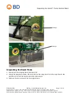
7. Lift the motor control board and inspect for damaged or separated bezel posts.
If there are damaged or separated bezel posts, the bezel must be replaced. If there are
no damaged or separated bezel posts, continue to Step 8.
8. Reinstall the motor control board. Refer to the technical service manual for reassembly
instructions. Continue to Reassembling and Testing the Alaris™ Pump Module on
Bezel posts


