Bayer HealthCare ON DEMAND Maintenance Manual Download Page 15

Step 2:


Use the correct element with the right Pump.

•  LS uses 15 (small), IP uses 73 (large).

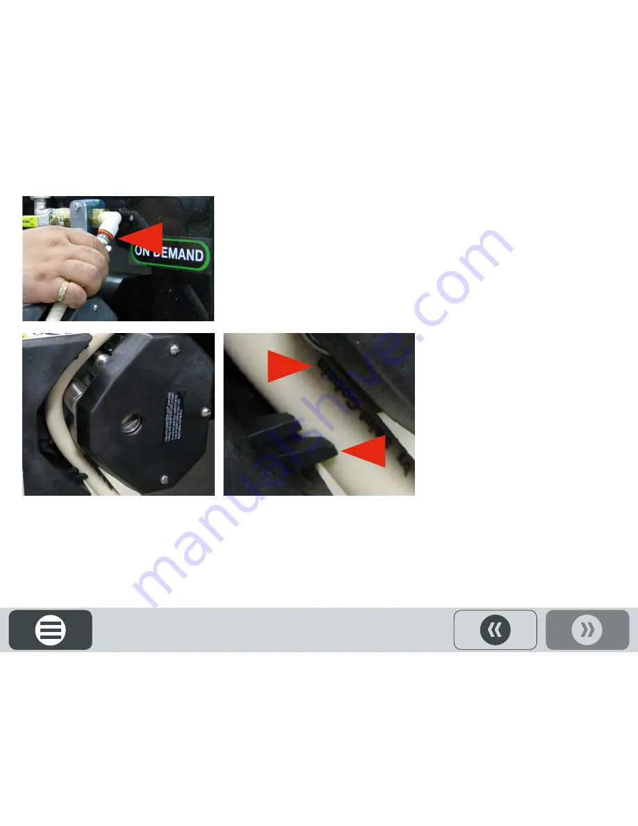
•  Insert one end of the factory supplied Pump Element into the orange Fitting Receptacle on the Pump Treatment Valve 

Vibration Mount, as shown.

Step 3:


Insert the Pump Element onto the Pump Head 

Rollers, as shown. 

•  Ensure Pump Element fits behind Pump Head Clips


15

Summary of Contents for ON DEMAND

Page 1: ...ON DEMAND MAINTENANCE GUIDE ...

Page 2: ...PICTOGRAMS Each Signifier displayed here is specific to this User Manual PM Checklist Menu Gearmotors Tip Previous Note Advance Example 2 Rotary Heads Drum Frame Control Panels Pump Stations ...

Page 3: ...MENU Drum Frame Control Panels Pump Stations This is an interactive PDF To fastforward to a chapter of interest click on the icon tiles Rotary Heads Pictograms Gearmotors PM Checklist 3 ...

Page 4: ...sfactory for the full service life of the reducer Seed Transition Quick Clean out Step 1 Remove the Seed Transition Place one hand on the transition and use the other to unlatch the three clamps holding the transition onto the bottom of the Atomizer section Step 2 Clean the Seed Transition Use a rag to wipe down inside the Seed Transition and a putty knife to scrape any residue build up 4 ...

Page 5: ...dup as shown left Replace the atomizer on the shaft Push it up on the shaft until it touches the chemical tube then back it off a little Tighten the nut Step 4 Replace the clean Transition under the Atomizer Housing Align the Transition to the back lip of the Housing and ensure each clamp is in line with the grooves on the transition Close each Clamp to securely fasten the transition in place 5 ...

Page 6: ...om both sides of the Drum Use a 7 16 wrench to loosen the four bolts that hold the Drum Guard in place Step 2 Use a grease gun to lubricate each bearing zerk There are nine pillow block bearings five on the drive shaft side and four on the idler side 6 ...

Page 7: ...4 An option is to add discard seed and letting that mix either with or without the hot water to clean the drum to the metal Step 5 Dispose of water and seed responsibly according to state and local regulations DO NOT RUN RINSE WATER DOWN THE DRAIN Step 3 Align the drum guard Align the drum guard properly with the channel in the middle of the drum guard groove as shown Step 4 Fasten Drum Guards Fas...

Page 8: ...gulations Line Rinse Step 1 If there is chemical in the lines run the pump in reverse and recover product Remove the Keg from the Scale Remove the Plumbing Assembly from the Keg Ulock by pulling the Handle UP then twist and pull the Assembly out of the Keg Step 2 Twist the Rinsing Socket onto the end of the Plumbing Assembly Then lock down the handle push DOWN 8 ...

Page 9: ...n the scale when priming the line Step 5 This will require two people Hold the Treatment Line in a 5 gallon bucket On the MAIN SCREEN touch the Pump Station graphic icon that requires rinsing navigates to the STATION 2 PUMP DETAIL SCREEN Step 4 Disconnect the treatment line from the Chemical Inlet Assembly Push in the orange fitting and pull out the tubing 9 1 2 ...

Page 10: ... each Pump Station used Complete Line Rinse Step 1 Remove the 2 screws that holds the Chemical Inlet on the Treating Head Place the Chemical Inlet Assembly connected to the Treatment Line in a 5 gallon pail as shown PRIME LINE Step 2 On the MAIN SCREEN touch the Pump Station graphic icon that requires rinsing navigates to the STATION 2 PUMP DETAIL SCREEN 10 1 2 ...

Page 11: ...each Pump Station used Step 4 Clean Chemical Inlet Assembly Use a wrench to remove the nut on the end of the Chemical Inlet Assembly Use a factory supplied tube brush to thoroughly clean the inside of the Chemical Inlet Assembly Replace nut on the Chemical Inlet Assembly Step 5 Replace the Chemical Inlet Assembly on the Treating Head Tighten screws 11 PRIME LINE ...

Page 12: ...shown when the Pump is not in use to avoid forming flat spots in the element Air Release Valve Step 1 Approximately once a year clean out the Air Release Valve on all Pump Stations Use 1 2 wrench to loosen six bolts and washers on top of the Air release Valve 12 ...

Page 13: ...ap off Use a screwdriver to carefully pry the cap off the housing use protrusions Do not damage the gasket Remove the cover Step 3 Clean and inspect the cover Especially inspect the small rubber washer for wear 13 ...

Page 14: ...When storing the Pump in subfreezing temperatures flush with products that prevent freezing such as RV Antifreeze or diluted windshield washer fluid Warning Failure to clean the Pump properly or com pletely drain all liquid from the pump and lines after use may damage the Pump and void any warranties expressed or implied Pump Element Replacement Step 1 Pump Elements should be replaced annually Ope...

Page 15: ... uses 73 large Insert one end of the factory supplied Pump Element into the orange Fitting Receptacle on the Pump Treatment Valve Vibration Mount as shown Step 3 Insert the Pump Element onto the Pump Head Rollers as shown Ensure Pump Element fits behind Pump Head Clips 15 ...

Page 16: ...ent into the orange Fitting Receptacle on the In line Strainer Vibration Mount as shown Step 5 Close Pump Head Handle is in the UP position as shown In line Filter Step 1 Periodically remove inspect and clean out the in line filter assembly on the Pump Station 16 ...

Page 17: ...Y IMPORTANT Failure to clean the treating system including all accessories properly or failure to completely drain all liquid chemicals from the Pump and Treatment lines after use may cause damage to the equipment and void the warranty Step 2 Open Filter Basket Place a drip pan or bucket beneath the filter and unscrew the Basket from the cap Remove the filter from the basket and clean thoroughly 1...

Page 18: ...y from the panel as shown Remove the filter and clean with a vacuum cleaner or replace the filter Repeat for air filter on the other top side of Controller Warning Power cord for HMI must remain plugged in to a live outlet at all times Battery back up system in HMI will need to be replaced if left unplugged for extended period 18 ...

Page 19: ...turn OFF the Main Control Power Lever as shown below Step 2 Turn OFF the HMI Control according to the instructions on the following pages NOTICE INTERNAL BETTERY REQUIRES POWER 24 7 TO SHUTDOWN COMPUTER FOR STORAGE GO TO SETUP SCREEN PRESS SHUTDOWN 19 ...

Page 20: ...ates to the System Configuration Screen 20 Batch Setup 1 2 Setup Inventory Reports Alerts Login Idle Stopped Stopped Bayer Engineering R D 81 Status PLC Status Comm Current User ENGR 12 18 2017 1 51 34 PM 78 dBm Seed Wheel Drum System Status Seed Present ...

Page 21: ...fig 12 18 2017 1 51 34 PM Exit Charts Clean Screen SYSTEM CONFIGURATION SCREEN Step 1 Touch the Shutdown button icon navigates to the Shutdown Screen 21 System Configuration Screen PLC Revision 4 11 15 HMI Revision 4 11 15 Show Seed Quantity on Batch Report X ...

Page 22: ...on program and turn the computer off 22 Shudown Drum Settings Pump Stations Seed Wheel Treater Config 1 51 34 PM Exit Charts Clean Screen System Configuration Screen PLC Revision 4 11 15 HMI Revision 4 11 15 Warning This will exit the application and turn the computer off Are you sure you want to do this Yes X No ...

Page 23: ...SDA H1 Biodegradable CLP E320 Water pollution class O Required maintenance tools 9 16 Wrenches 2 6mm Allen Wrench 8mm Allen Wrench Oil Pan THOROUGHLY DRAIN OIL WHILE IT IS WARM Step 1 Use a 6mm Allen Wrench to remove the oil drain plug located on the bottom of the Gear Motor An access hole is provided on the Motor Mount to gain access to the oil drain plug without having to remove the entire Gear ...

Page 24: ...main on during treating season Clean drum if needed Kegs may remain connected and on the scales START OF DAY Close pump pressure levers ensure proper placement of pump element Open valve lever Jog lines as needed to top up prime WEEKEND SHUTDOWN Reverse pumps to clear all product from lines Release pump element lever to prevent damage to element HMI and Main Control panel may remain on Clean drum ...

Page 25: ...move filters on pump stations and clean Replace all pump elements ensure proper size of replacements 73 for IP pump and 15 for LS pump Replace chemical lines to treater as needed Remove transition chute and clean atomizer and chamber Clean Air release valves Clean Drum Grease pillow block bearings Clean air filters on main panel Power down main panel and HMI HMI Must remain plugged in to a live ou...

Page 26: ...MN 5379 USA Telephone 1 952 445 6868 Toll free 1 855 363 3152 Visit us on www seedgrowth bayer com BayerTM the Bayer CrossTM OnDemandTM and Bayer SeedGrowthTM are registered trademarks of Bayer SGRONDEMANDMAINTENANCE08012018 Products Coatings Equipment Services ...

Reviews: