38
POWER SUPPLY DIAGNOSTICS
12
Minimize load on power supply and isolate short
Unplug the 3 cables from the power supply going to all boards and cables.
This will leave the power supply all by itself.
- If power supply still does not power on, replace power supply (AAPS1013-SNW)
- If power supply does turn on with all cables disconnected:
Plug in the Newgen Board to the power supply, but unplug all of the outputs from the board.
Turn on game and verify the power supply turns on.
- If it does not turn on, replace the Newgen Board (AANEWGEN1-RBN)
- If it does turn on, then plug in one cable at a time to the board.
If the power supply does not power on when a specific cable is plugged in—follow that cable
and fix short.
Power Strip
AACE6919
Flashing Light Bulb Theory
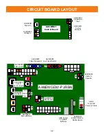
The control board in the upper back of game controls the flashing light bulbs on the playfield.
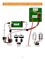
This control board receives 5 volt DC from the red and black wires on cable #’s: CE6904, CE6909, CE6905,
from power supply (AAPS1023-SNW)
It receives 12 volts on the green and yellow wires from the terminal block on cable # CE6904
The terminal block receives power from the powers supplies on cable #’s: CE6937, CE6926
Control board communicates to the Newgen board through cable # CE6944, CE6905, CE6909, & CE6943.
The flashing light bulbs are controlled by the control board using a signal that originates from CE914 to the
top bulb in the large light ring. The bulbs are daisy chained together around the large light ring, then to the
center ring though cable #’s: CE6948 & CE6947. Once around the center small ring, the signal goes up to the
marquee through cable #’s: CE6948, CE6938, CE6947.
There are 4 special flashing light bulbs in the game ( 3 in large ring and 1 in the marquee) that are supplied
24 volts DC. The first bulb in the chain, (top of the la
rge ring) is this special bulb. (Part # AACE6946)
These 4 bulbs are supplied 24 Volts DC from the terminal block through cables #’s: CE6939, CE6940,
CE6941, & CE6942. Refer to wiring diagram.
The terminal block receives 24 volts from a power supply (part # A5PS6900) through cable #’s CE6926 &
CE6937.
The other 128 flashing bulbs are the same and interchangeable for troubleshooting. (Part # A5LD6900)
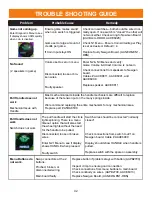
1.) Verify AC power to game. Check power strip in front door.
The rocker switch should be illuminated.
2.) Check power in connection to power supply.
3.) Ensure Power Supply switch is set to 115V (or 230V)
(
Some model power
supplies may not have this)
4.) Ensure Power switch is on.
5.) Ensure fan is turning.
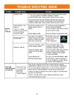
If power supply fan is turning and there is no 12 Volt out:, replace power supply (AAPS1013-SNW)
If power supply fan is not turning, then continue to “Verify Power to Motherboard”
6.) Ensure the Green and black wires are tied together on the power supply.
This will turn on the power supply with no load or signal from game.


