


9.0
Installation of pump station
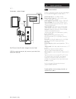
9.7
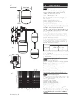
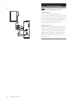
Installing the safety group
Connect the safety group (Fig 20 Item 1) with the washer
(Fig 20 Item 2) enclosed to the connection on the hydraulic
station return isolating valve assembly (Fig 20 Item 3).
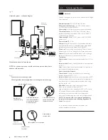
9.8
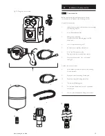
Connecting the solar expansion vessel
Mount the solar expansion vessel (Fig 21 Item 1) adjacent to
the hydraulic station (Fig 21 Item 2) so that the vessel can be
connected to the vessel connection of the safety group (Fig 21
Item 3) using the flexible pipe (Fig 21 Item 4) supplied.
(
NOTE:
Solar expansion vessel, mounting bracket, self sealing
connection and flexible pipe are supplied in the Ancillary
Components kit).The vessel must be mounted as shown
(connection to top) and securely supported using the wall
bracket supplied.The self sealing vessel connection should be
screwed onto the vessel connection before connecting the
flexible pipe (Fig. 21 Item 5).
DO NOT
replace the solar expansion vessel with either a
potable water expansion vessel or boiler sealed system vessel.
Solar expansion vessel has a pre-set pressure of 2.5 bar and
must be adjusted to suit your installation.
The charge pressure at the solar expansion vessel should be
adjusted such that when not under load the charge pressure is
0.7 bar above the static system head (the height of the top of
the collector panels above the hydraulic station). A one metre
head represents 0.1 bar. However, the charge pressure should
be at least 1.5 bar.
The maximum static system head is 15m (1.5 bar).
9.9
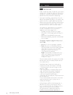
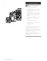
Connecting pipework
Connect the flow and return pipes to the collectors and to the
cylinder via compression fittings (Fig 22 Item 1). Fittings are for
22mm o/dia pipe.
Support the pump assembly when tightening
connections.
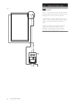
Run a pipe (Fig 22 Item 2) from the exit opening in the
pressure relief valve (Fig 18 Item 3) to a suitable container
(Fig 22 Item 4) and secure it. Ensure the pipe enters the
container to a level which will allow a safe discharge of fluid in
the event of the pressure relief valve opening. Ensure the
catchment container can be removed after the pipe has been
secured. After commissioning, add the pressure relief catchment
vessel warning label to the container. Align the arrows on the
label with any remaining fluid in the container.
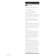
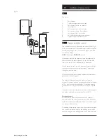
Installing a drain valve
Install a device for draining the solar heating system
(tee piece with drain valve, Fig. 23) into the flow and return at
the lowest point in the solar heating system. Drain valve must
be suitable for glycol, 180° C and 6 bar.
Connecting the solar cylinder
For detailed installation instructions refer to the installation
instructions supplied with the solar cylinder.
18
© Baxi Heating UK Ltd 2008
1
2
3
4
5
1
2
3
3
2
4
1
Flow
from
panel
Return
to
panel
Flow
to
cylinder
Return
from
cylinder
Flow to cylinder
Return from cylinder
Return to hydraulic station
Fig. 20
Fig. 22
Fig. 23
Fig. 21
Commissioning Label


