


22
© Baxi Heating UK Ltd 2008
10.0
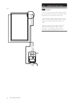
Installation of solar controller
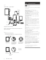
10.7
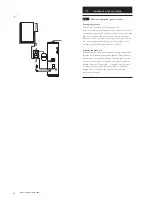
Connection of temperature sensors
The sensor with black silicone sheathing must be used for
the solar collector sensor.
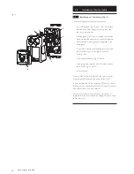
The controller uses precise platinum temperature sensors type
PT1000.The controller is supplied with 3 sensors.
Installation / cabling of temperature sensors:
Mount the sensors in the pockets provided in the collector
and storage tank.
The wires of the temperature sensors can be lengthened. Up
to 15m long you need a 2 x 0,5mm
2
cross-section, up to 50m
2 x 0,75mm
2
. In the case of long connections (collector)
shielded extension lead must be used.
DO NOT
run sensor leads adjacent to mains carrying voltage
conductors (at least 50mm separation is recommended).
Temperature sensors are connected according to the
appropriate terminals, refer to Fig 25.
The sensors are polarity free.
Sensors
MUST NOT
be connected to the 230/240V~
terminals.
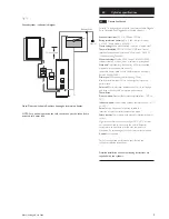
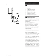
10.8
Control of Auxiliary heat input
When using the reheat function the operation of the auxiliary
heat input device can be controlled via output A3 from the
controller.
The reheat sensor cable should be connected to terminal T5
of the solar controller and the sensor element inserted into
the controls pocket at the auxiliary heater level (see Fig. 11).
NOTE:
The maximum switching current of the controller
is 2 Amp in total, 1 Amp per output. If switching an electrical
immersion heater or using a 3 port valve system this
MUST
be done via a relay
(see Fig. 28 Block Wiring Scheme C or E)
order accessory code No. 5122765.
If using a boiler for auxiliary input, the output from the reheat
function should be integrated into the boiler control circuit.
3A Fused Supply
L
1
1
7
10
3
1
2
3
E
2
3
4
5
6
7
8
9
10
Terminal Box (Not supplied)
2
3
2
3
5
1
2
3
7
6
N
E
L
N
E
SL
L
N
E
DHW ON CH ON
Boiler Terminal Strip
Programmer
1
Solar Cylinder Auxiliary Controls
6
9
2
1
2
N
Room Stat
1
8
Solar
Controller
Boiler
Immersion
3
1
2
E
Solar O/Temp Cutout
3
8
2
PE
L
N
Solar Differential Controller
11
A1
12
N
T1
T2
T4
WMM
4
2
3
L
N
E
CH Pump
A1
N
PE
11
12
E
Solar Pump
3
2
10
1
G/Y
BL
BR
GR
DHW 2 Port Valve
5
OR
3
2
9
1
G/Y
BL
BR
GR
CH 2 Port Valve
5
OR
See Fig. 21
3A Fused Supply
L
1
1
7
10
3
1
2
3
E
2
3
4
5
6
7
8
9
10
Terminal Box (Not supplied)
2
3
2
3
5
1
2
1
9
N
E
N
E
SL
L
N
1
2
Boiler Terminal Strip
Programmable Room Stat
1
L
4
PL
Solar Cylinder Auxiliary Controls
1
3
1
2
E
Solar O/Temp Cutout
8
3
8
2
PE
L
N
Solar Differential Controller
11
A1
12
7
2
N
A3
N
T1
T2
T4
T5
WMM
4
2
3
L
N
E
CH Pump
A1
N
PE
11
12
E
Solar Pump
3
2
10
1
G/Y
BL
BR
GR
DHW 2 Port Valve
5
OR
3
2
9
1
G/Y
BL
BR
GR
CH 2 Port Valve
5
OR
See Fig. 21
3 Amp Fused Supply
L
1
1
2
3
4
5
6
7
8
9
10
Terminal Box (Not supplied)
2
3
N
E
13 Amp Fused Supply
L
4
5
6
N
E
1
8
3
1
2
E
Solar O/Temp Cutout
7
5
6
L
N
E
Immersion Heater
A3
N
4
1
5
CoM
Auxiliary Immersion Heater Relay
7
No
3
8
2
PE
L
N
Solar Differential Controller
11
A1
12
N
A3
N
T1
T2
T4
T5
WMM
A1
N
PE
11
12
E
Solar Pump
See Fig. 20
Relay
PL
4
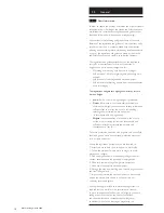
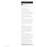
Fig. 28
Block Wiring Schemes
A.
Solarflo
TM
in conjunction with auxiliary heating by boiler - no reheat
control by solar controller.
B. Solarflo in conjunction with auxiliary heating by boiler - reheat control
via solar controller.
Note:
If boiler has PL - Pump Live connection, pump must be connected to
this (4), if not Pump Live should be connected to SL (5).
C. Solar Cylinder with auxiliary heating by immersion heater.
NOTE: Arrows identify wires which go to wiring centre terminal block.