Baxi Bermuda 45/3 M Installation And Servicing Instructions Download Page 33

CHANGING COMPONENTS - Page 33
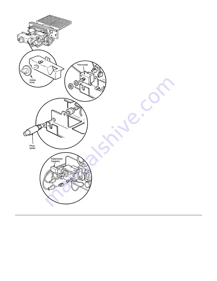
Thermostat

MANUAL CONTROLS ONLY

Remove the control knob. Undo the screw retaining the
valve cover and remove the cover.

Undo the locknut retaining the thermostat to the controls
mounting bracket. Ease the thermostat away from the
bracket and disconnect the electrical connections noting
their positions.

Reassemble in reverse order.

Piezo Igniter Unit

MANUAL CONTROLS ONLY

Remove the controls heat shield from its retaining clips if not
already done so.

Remove the control knob. Undo the screw retaining
the valve cover and remove the cover.

Pull the igniter lead off the piezo and undo the
plastic locknut. Remove the piezo igniter unit.

Reassemble in reverse order.

Suppression Capacitor

MANUAL CONTROLS ONLY

The controls may remain in situ but the controls heat shield
must be removed from its retaining clips.

Remove the control knob. Undo the screw retaining the
valve cover and remove the cover.

Note the positions of the electrical connections on the valve
and remove them.

Remove the capacitor connections from the
valve

Reassemble in reverse order.

Summary of Contents for Bermuda 45/3 M

Page 1: ...No 241794 Iss 9 6 00 Baxi Bermuda 45 4 M G C No 44 077 71 Baxi Bermuda 57 4 M G C No 44 077 72 Baxi Bermuda 45 4 E G C No 44 077 73 Baxi Bermuda 57 4 E G C No 44 077 74 These Instructions must be read in conjunction with those for the separate Firefront Installation And Servicing Instructions ...

Page 2: ...p new ideas using the latest technology with the aim of continuing to make the products that customers want to buy Baxi is also the largest manufacturing partnership in the country Everyone who works at the company has a commitment to quality because as shareholders we know that satisfied customers mean continued success We hope you get a satisfactory service from Baxi If not please let us know Th...

Page 3: ...ystems Overheat Thermostat Pumped Heating Gravity Hot Water Gas Connection Electrical Connection Making the Electrical Connection Refilling the Controls Flue Connection Completion Commissioning the Appliance PAGE 23 24 Annual Servicing PAGE 25 28 Removal of Firefront Removal of Controls Cleaning the Lint Arrestor Cleaning the Burner Main Injector Cleaning the Pilot A S D Assembly Cleaning the Heat...

Page 4: ...5 for 45 4E 57 4E Baxi Part No 234885 for 45 4M 57 4M Installation The installation must be carried out by a CORGI Registered Installer or other Competent Person and be in accordance with the relevant requirements of GAS SAFETY Installation and Use REGULATIONS the BUILDING REGULATIONS Scotland Consolidation the LOCAL BUILDING REGULATIONS the current I E E WIRING REGULATIONS and the bye laws of the...

Page 5: ...rmuda 45 4 and 57 4 Boilers The seasonal efficiency SEDBUK are 45 4M 72 7 45 4E 76 8 57 4M 71 8 57 4E 75 8 This value is used in the UK Government s Standard Assessment Procedure SAP for energy rating of dwellings The test data from which it has been calculated has been certified by 0086 ...

Page 6: ...nes given in B57593 1992 Treatment of water in domestic hot water central heating systems This must involve the use of a proprietary cleanser such as BetzDearborn s Sentinel X300 or X400 or Fernox s Superfloc Full instructions are supplied with the products but for immediate information please contact BetzDearborn on 0151 420 9563 or Fernox on 01799 550811 For long term protection against corrosio...

Page 7: ...f the system Fully Pumped System The sizes of the system pipes should be determined by normal methods BS 5449 The open vent pipe should be a minimum of 22mm and must rise continuously to a point above the feed and expansion tank The flow pipe from the boiler may form part of the vent pipe No part of the open vent should contain a valve The cold feed pipe 15mm mm should preferably be connected to t...

Page 8: ...d by normal methods BS 5449 28mm pipe is recommended for the gravity circuits The gravity flow pipe should rise vertically as close as possible to the boiler avoiding sharp bends and tight elbows The open vent pipe should be a minimum of 22mm and must rise continuously to a point above the feed and expansion tank The flow pipe from the boiler may form part of the vent pipe No part of the open vent...

Page 9: ...may not be installed in bathrooms shower rooms bedrooms or bed sitting rooms Fireplace Surround If a fireplace surround is to be used it must be centrally placed and have opening sizes and a vertical flat area as shown in the firefront Installation and Servicing Instructions Maximum fireplace opening sizes are preferable for ease of installation and service NO SURROUND The appliance can be fitted ...

Page 10: ...y swept The flue must be protected with a 125mm 5in flexible liner The bottom of the liner should terminate 500mm 20in above the base of the builders opening The flue must be sealed between the liner and the brickwork at both the top and bottom An approved terminal must be installed ACID RESISTANT LINERS A flue constructed of acid resistant liners is satisfactory provided the size requirements are...

Page 11: ...tected It is preferable to route the gas supply pipe to the right hand side of the builders opening It must be routed so as not to restrict the installation and servicing of the appliance Electrical Supply External wiring must be correctly earthed polarised and in accordance with current lEE wiring regulations The mains supply is 230V 50Hz fused at 5 A NOTE The method of connection to the electric...

Page 12: ...te the input cable from the left hand side of the builders opening The cable can be secured to either the boiler base or fire support plate using the P clip supplied in the kit NOTE Polarity of the appliance MUST be correct otherwise the appliance will not operate correctly ...

Page 13: ...his operation is performed most easily with the boiler on its back Lift out the 3 heat exchanger baffles noting their orientation Lift the heat exchanger from the appliance and remove the side blanking plate Transfer the 3 sealing rings from the holes in the left hand side of the boiler to those in the right Rotate the heat exchanger to place the water connections at the right hand side return the...

Page 14: ... V mark on the front centre of the appliance base The appliance positioning into the opening is variable to cater for pipe flue alignment The boiler may be positioned by locating the front face of the fireplace anywhere between the two V marks on either side of the appliance base Securing The Boiler Check the alignment within the opening is correct The hearth should be drilled as follows Mark the ...

Page 15: ...ETURN connect the pumped return into the adaptor using the nut and olive Fit a 1 in x 22mm threaded adaptor into the higher tapping position marked FLOW connect the pumped flow into the adaptor Fit a 1 in plug to the remaining connection Follow the instructions under System Details regarding the vent pipe and cold feed Overheat Thermostat For systems requiring an overheat thermostat a modification...

Page 16: ...5º either side of the vertically downward plane Connect the pumped return to the 22mm compression fitting of the injector tee Take the gravity hot water return pipe to a level beneath that of the injector tee and connect upwards to the 28mm branch of the injector tee as shown Connect the pumped flow to the connection marked FLOW Connect the gravity flow to the remaining connection The gravity flow...

Page 17: ... by the same isolator NOTE The polarity of the electrical supply must be correct otherwise the appliance will not operate OVERHEAT THERMOSTAT Where an overheat thermostat modification kit is required the wiring instructions supplied in the kit must be followed Making the Electrical Connection On installations where the firefront requires a permanent live locate the kit in the firefront carton and ...

Page 18: ...nnect the wire from the fire front kit as indicated Brown live to L Blue neutral to N Green and yellow earth to 5 Re fit both cable clamps ensuring that the outer insulation is securely held and re fit the socket cover For installations not requiring a permanent live ie radiant fire fronts proceed as follows Connect the inlet supply cable as indicated Control system switched live to SL Control sys...

Page 19: ...gth to connect the wire to the earth terminal on the mounting bracket Remove the side cable clamp and connect the wire from the firefront kit as indicated Brown live to L2 Blue neutral to N Green Yellow earth in a similar manner to the mains earth wire Refit both cable clamps ensuring that the outer insulation is securely held and refit the socket cover For installations where no permanent live is...

Page 20: ...of the appliance ELECTRONIC CONTROLS MODELS Replace the combustion box door and secure with the four screws Ensure that the sensing pipe locates over the pilot breather sealing washer The screws must be tight to achieve the required seal and to ensure correct operation of the Atmospheric Sensing Device Insert the thermostat sensor and retaining strip through the rubber seal in the door into the he...

Page 21: ...rect operation of the Atmospheric Sensing Device Insert the thermostat phial through the rubber seal in the door into the heat exchanger thermostat pocket Engage the capillary in the routing clips Connect the input socket to the valve plug and locate the socket in the mounting bracket slot Refit the socket cover using the screw previously removed Refit controls heat shield If a radiant appliance i...

Page 22: ...ded in the kit Seal the flue into the flue outlet socket Completion Seal off any secondary openings within the builders opening after wrapping the gas and water pipes where they pass through the brickwork and within the opening itself B S 5871 Part 1 If required see page 12 secure the cable to the boiler using the P clip and screw to either boiler base see page 20 or fire support plate The fire su...

Page 23: ... No adjustment is possible Operate the burner by turning the boiler thermostat knob to the HIGH setting and check the operation of the flame failure device by turning the grey button Grey Push clockwise The burner and pilot should extinguish Turn the boiler thermostat to the O position wait 3 minutes and relight the pilot as previously described Turn the boiler thermostat to HIGH and check the bur...

Page 24: ...s without permanent live i e radiant firefront installations where terminals L and SL have been connected using the link wire the first two orange lights will illuminate simultaneously when the switched live is supplied Operate the burner and allow the system to reach normal operating temperature Make further checks for leaks and check the burner setting pressure adjusting if necessary This is don...

Page 25: ...front instructions for the removal of the firefront Removal of Controls ELECTRONIC CONTROLS MODELS Remove the thermostat sensor and retaining strip from the heat exchanger and carefully remove the sensor wire from its routing clips Remove the controls heat shield from its retaining clips Remove the four screws retaining the combustion box door and remove the door Lift and remove the injector insul...

Page 26: ...Lift and remove the injector insulation pad Slacken the screw securing the plug and socket mounting bracket to the valve mounting bracket Pull the mounting bracket to the left and disconnect the controls plug Lay the mounting bracket and cable to one side Disconnect the union nut from the gas service tap Slacken the two screws securing the controls to the base tray and remove the screws securing t...

Page 27: ...A S D Assembly Note No attempt should be made to clean the device using any hard tools including pins or wire The thermocouple electrode and pilot burner that make up the pilot assembly are not replaceable as separate items If any part is damaged then the pilot assembly should be replaced During annual appliance servicing the pilot assembly should be inspected for damage to any of the component pa...

Page 28: ...ong with the insulation Clean between the heat exchanger fins and flueways with suitable brushes and remove any deposits from the combustion box base tray Clean away any lint or other deposits from the boiler hood and builders opening Reassemble the insulation in reverse order and refit the baffles Reassemble the appliance in reverse order re commission the appliance and check for gas soundness Co...

Page 29: ...ng Flame Sensing Lead ELECTRONIC CONTROL MODELS Remove the three screws holding the controls box cover on and remove the electrode lead from its terminal on the PCB and the sensing probe The lead has a white sleeve at the probe end Reassemble in reverse order Ignition Lead ELECTRONIC CONTROL MODELS Remove the three screws holding the controls box cover on and remove the electrode lead from its ter...

Page 30: ...wire Remove the two screws holding the valve to the controls mounting bracket adjacent to the union nut and tailpiece Undo the pilot feed pipe nut from the valve Remove the three screws holding the burner feed pipe to the valve being careful not to lose or damage the O ring seal Remove the valve from the controls mounting bracket Remove the tailpiece and union nut from the original valve and fit t...

Page 31: ...wo screws holding the valve to the controls mounting bracket adjacent to the union nut and tailpiece Undo the pilot feed pipe nut and thermocouple from the valve Remove the three screws holding the burner feed pipe to the gas valve being careful not to lose the O ring seal Remove the valve from the controls mounting bracket Remove the tailpiece and union nut from the original valve and fit to the ...

Page 32: ...s if not already done so Remove the ASD thermocouple nut at the rear of the valve Remove the ignition lead from the ASD electrode and flame sensing lead on electronic models Undo the pilot feed pipe at the ASD Remove the three screws holding the burner feed pipe flange to the underside of the valve Separate the valve and burner assemblies Remove the lint arrestor Undo the two screws holding the AS...

Page 33: ...ts retaining clips if not already done so Remove the control knob Undo the screw retaining the valve cover and remove the cover Pull the igniter lead off the piezo and undo the plastic locknut Remove the piezo igniter unit Reassemble in reverse order Suppression Capacitor MANUAL CONTROLS ONLY The controls may remain in situ but the controls heat shield must be removed from its retaining clips Remo...

Page 34: ...iometer to the controls mounting bracket and remove the potentiometer by disengaging its locating tab Reassemble in reverse order Printed Circuit Board ELECTRONIC CONTROLS ONLY Remove the controls heat shield from its retaining clips if not already done so Undo the three screws retaining the control box cover and remove the cover Disconnect the three multi pin plugs flame sensing lead and ignition...

Page 35: ... 45 4 M Stereomatic B20 Injector Burner 45 4 E Stereomatic B20 Injector Burner 57 4 Stereomatic B21 Injector Burner 57 4 Stereomatic B21 Gas Valve Manual Gas valve Electronic Potentiometer Leads E models Sensor Thermostat E models Printed Circuit Board E models Pilot A S D Assembly M models Pilot A S D Assembly E models Thermostat Boiler M models Knob Thermostat Boiler M models Lead Electrode Lead...

Page 36: ...FAULT FINDING 57 4M 45 4M Page 36 ...

Page 37: ...FAULT FINDING 57 4M 45 4M Page 37 ...

Page 38: ...FAULT FINDING 57 4E 45 4E Page 38 ...

Page 39: ...FAULT FINDING 57 4E 45 4E Page 39 ...

Page 40: ...FAULT FINDING 57 4E 45 4E Page 40 Click here for Helplines ...

Reviews: