9137300990 Rev J
BE1-81O/U Functional Description
3-3
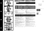
Frequency (HZ)
dB
12
13
14
15
16
17
18
12
40
60
80
100
120
140
160
180
200
D2856-24
Figure 3-2. Band-Pass Filter Characteristics
Maximum Period Difference Logic
This logic includes an address resister and programmable, read-only memory (PROM). Following the
EOPR pulse from the minimum period difference logic, the address register counts 1 MHz clock pulses to
address 4096 data words stored inn the PROM. Completion of the count represents the period of the
30 Hz minimum detectable frequency limit. If zero-cross pulses have properly occurred before the count
ends, the measured frequency converter computes the actual frequency, within the frequency limits,
utilizing the corresponding data words stored in the PROM.
If sensed frequency decreases to less than the 30 Hz minimum frequency limit (zero-cross pulses occur
after the counts are completed) for three consecutive cycles, the measured frequency converter
computes the frequency at the minimum frequency limit. The definite time delay is not affected by the
frequency limit being exceeded.
Measured Frequency Converter
The measured frequency converter changes the data word from the maximum period difference logic to a
four-digit, binary-coded decimal (BCD) number that represents the actual sensed frequency (with an
accuracy of 0.01 Hz) within the 30 to 80 Hz limits. The BCD frequency data bus passes this data to the
frequency comparator logic of each setpoint.
Frequency Comparator Logic
This logic compares the BCD number representing the actual sensed frequency with the Frequency
Selector Switch setting on the front panel. An output is triggered when the sensed frequency decreases
below the setpoint (Over/Under Selector Switch set to U), or when the sensed frequency increases above
the setpoint (Over/Under Selector Switch set to O). The resultant output consists of an enabling level that
starts a count-up timer and lights the front panel Pickup Indicator.
Definite Time Delay Logic
The enable signal (representing a detected over or underfrequency condition) from the frequency
comparator logic initiates the count of zero-cross pulses. After three consecutive cycles exceed the
pickup setting, the definite time delay logic lights the Pickup Indicator. When the front panel Time Delay
Selector Switch setting is reached, the logic energizes the setpoint output relay. The total time delay, with
seconds-type timing selected, is the Time Delay Selector Switch setting plus one cycle of the sensed
input plus 0.008 seconds (output relay delay). The Pickup LED remains lit until the frequency condition is
corrected. When the sensed frequency returns to normal for three cycles, the Pickup LED and output
relay reset.
Summary of Contents for BE1-81O/U
Page 2: ......
Page 6: ...iv BE1 81O U Introduction 9137300990 Rev J This page intentionally left blank...
Page 16: ...1 8 BE1 81O U General Information 9137300990 Rev J This page intentionally left blank...
Page 20: ...2 4 BE1 81O U Controls and Indicators 9137300990 Rev J This page intentionally left blank...
Page 26: ...3 6 BE1 81O U Functional Description 9137300990 Rev J This page intentionally left blank...
Page 31: ...9137300990 Rev J BE1 81O U Installation 4 5 Figure 4 4 S1 Case Dimensions Rear View...