background image

3. Intended Use

The parking aid serves to signal obstacles when parking or driving backwards. The system 

functions using ultrasonic sensors.
Item no. 2162728 signals the distance to possible obstacles acoustically.
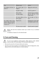
With item no. 1719341, possible obstacles indicate possible obstacles acoustically and optically 

on an LED. This makes it easy to detect the distance to and the direction of the obstacle. The 

acoustic warning signal can be deactivated.

This product may only be operated if it is connected to a 12V DC car power supply with the 

negative terminal of the car battery connected to the body. It may only be installed and operated 

in passenger cars and motor lorries provided with this kind of supply voltage.
For safety and approval purposes, you must not rebuild and/or modify this product. If you use 

the product for purposes other than those described above, the product may be damaged. In 

addition, improper use can result in short circuits, fires, electric shocks or other hazards. Read 

the instructions carefully and store them in a safe place. Make this product available to third 

parties only together with its operating instructions.
All company names and product names are trademarks of their respective owners. All rights 

reserved.

4. Delivery Content

•  Acoustic parking system
•  Operating instructions

1

Up-to-Date Operating Instructions

Download the latest operating instructions at www.conrad.com/downloads

 or scan the QR code 

shown. Follow the instructions on the website.

18

Summary of Contents for 1719341

Page 1: ...erating Instructions Acoustic Parking System Item No 2162728 Item No 1719341 Page 16 28 Mode d emploi Syst me acoustique d aide au stationnement N de commande 2162728 N de commande 1719341 Page 29 42...

Page 2: ...mfang 4 5 Sicherheitshinweise 5 a Allgemeine Hinweise 5 b Angeschlossene Ger te 6 6 Bedienelemente 7 7 Betrieb 7 a Vorbereitung 7 b Montage 8 c Anschluss 10 d Inbetriebnahme 11 e Anstreichen der Senso...

Page 3: ...bung Daran sollten Sie auch denken wenn Sie dieses Produkt an Dritte weitergeben Heben Sie deshalb diese Bedienungsanleitung zum Nachlesen auf Bei technischen Fragen wenden Sie sich bitte an Deutschla...

Page 4: ...u und der Betrieb in Pkws und Lkws mit einem Bordnetz das von den angegebenen Spezifikationen abweicht ist nicht gestattet Aus Sicherheits und Zulassungsgr nden d rfen Sie das Produkt nicht umbauen un...

Page 5: ...zen Sie es vor unbeabsichtigter Verwendung Der sichere Betrieb ist nicht mehr gew hrleistet wenn das Produkt sichtbare Sch den aufweist nicht mehr ordnungsgem funktioniert ber einen l ngeren Zeitraum...

Page 6: ...Sollten Zweifel ber die Auswahl des Einbauplatzes bestehen informieren Sie sich bitte bei Ihrem Kfz H ndler Vergewissern Sie sich vor der Ausf hrung von Befestigungsbohrungen dass hierdurch keine elek...

Page 7: ...ng 6 Lochbohrer 7 Ausgleichsringe f r Sensoren 7 Betrieb a Vorbereitung Durch den Einsatz von vier Ultraschallsensoren wird der R ckfahrbereich fast l ckenlos berwacht Die Sensoren m ssen daf r gleich...

Page 8: ...gteile eingeschr nkt wird Dies w rde eine Fehlfunktion nach sich ziehen Die Sensoren m ssen gleichm ig ber die Fahrzeugbreite verteilt montiert werden Der Abstand zwischen den Sensoren darf nicht gr e...

Page 9: ...lteilbezeichnung Wird die Reihenfolge vertauscht stimmt die Richtungszuordnung in der LED Anzeige 3 nicht berein 3Leitungen verlegen und Komponenten einbauen F hren Sie die Anschlussleitungen der Ultr...

Page 10: ...binden Sie die Stecker der Verbindungsleitungen 3 oder 4 mit der Buchse DISP an der Steuereinheit 1 Verbinden Sie die vier Stecker der Ultraschallsensoren A bis D in der richtigen Reihenfolge mit den...

Page 11: ...ufen Lo normale Lautst rke Hi laut eingestellt werden kann Einparksystem mit LED Anzeige und akustischem Warnsignal Best Nr 1719341 An der R ckseite der Anzeige befindet sich ein kleiner Schiebeschalt...

Page 12: ...ste Vorsicht geboten ist wenn Sie die Sensoren in der Farbe Ihres Fahrzeugs anstreichen wollen Einige Reinigungsmittel L semittel oder bestimmte Farben k nnen die Sensoren angreifen was zu Fehlfunktio...

Page 13: ...tsgang ist nicht eingelegt Legen Sie den R ckw rtsgang ein Die Z ndspannung ist nicht vorhanden Schalten Sie die Z ndung ein Die Verkabelung ist fehlerhaft Die Sicherung ist defekt berpr fen Sie die S...

Page 14: ...ktionen f hren k nnen Trennen Sie das Produkt vor jeder Reinigung von der Stromversorgung Reinigen Sie die Au ensensoren regelm ig um Fehlfunktionen zu verhindern Die Anzeige reinigen Sie am besten mi...

Page 15: ...h max 65 mA max 175 mA Erfassungsbereich 40 bis 140 cm 30 bis 200 cm Betriebstemperatur 20 bis 70 C 20 bis 70 C Abmessungen B x H x T Lautsprecher 51 x 39 x 26 mm Anzeige 135 x 30 x 27 mm Steuereinhei...

Page 16: ...18 5 Safety Instructions 19 a General Information 19 b Connected devices 20 6 Operating Elements 21 7 Operation 21 a Preparation 21 b Installation 22 c Connection 24 d Initial operation 25 e Reverse s...

Page 17: ...oduct to any third party Therefore retain these operating instructions for reference If there are any technical questions please contact International www conrad com contact United Kingdom www conrad...

Page 18: ...ssenger cars and motor lorries provided with this kind of supply voltage For safety and approval purposes you must not rebuild and or modify this product If you use the product for purposes other than...

Page 19: ...accidental use Safe operation can no longer be guaranteed if the product is visibly damaged is no longer working properly has been stored for extended periods in poor ambient conditions or has been su...

Page 20: ...ch a manner that neither the traffic safety nor the designed stability of the car is impaired If you are in doubt about where to install the device consult your car dealer Before drilling the attachme...

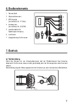
Page 21: ...r voltage supply 6 Hole cutter 7 Compensation rings for sensors 7 Operation a Preparation With the application of four ultrasound sensors the reverse drive space is almost completely monitored The sen...

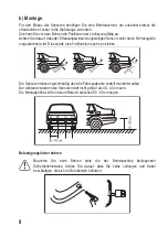
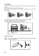
Page 22: ...not obstructed by vehicle parts This would lead to malfunctioning The ultrasound sensors must be installed evenly across the width of the vehicle The distance between the sensors may not exceed 30 to...

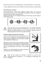
Page 23: ...idual parts If the sequence is mixed up the direction assignment of the LED display 3 is not correct 3Installing lines and components Guide the connection cables of the ultrasound sensors from the out...

Page 24: ...s of the ultrasound sensors A to D in the right sequence with the sockets A B C D of the control unit 1 Make sure that the letters on the cables and sockets are in the right sequence After you have ma...

Page 25: ...or approx 1 second Test the system prior to first use to familiarize yourself with the displays and signals Ask a second person to simulate the obstacle behind your car To do so switch on the ignition...

Page 26: ...p it functioning altogether The manufacturer and supplier will not be held responsible for any correction replacement or damage caused 2The following is our recommended painting procedure 1 Do not use...

Page 27: ...ror Disengage the reverse gear and engage it again reset The sensors are very dirty Clean the sensors regularly Repairs other than those described should only be carried out by an authorised specialis...

Page 28: ...rotection of the environment 11 Technical Data Item no 2162728 Item no 1719341 Input voltage 12V DC on board supply net with minus pole on ground Power consumption max 65 mA max 175 mA Detection area...

Page 29: ...ignes de s curit 32 a Informations g n rales 32 b Appareils connect s 33 6 l ments de commande 34 7 Fonctionnement 34 a Pr paration 34 b Installation 35 c Connexions 37 d Mise en service 38 e T tes de...

Page 30: ...ce produit un tiers Par cons quent conservez ce mode d emploi afin de pouvoir vous y r f rer ult rieurement Pour toute question technique veuillez vous adresser France email technique conrad france f...

Page 31: ...mis en service dans les voitures particuli res ou dans les poids lourds pr sentant cette configuration Pour des raisons de s curit et d homologation toute restructuration et ou modification du produit...

Page 32: ...t prot gez le de toute utilisation accidentelle Un fonctionnement s r ne peut plus tre garanti si le produit est visiblement endommag ne fonctionne plus correctement a t stock pendant une p riode prol...

Page 33: ...re ou la stabilit de construction du v hicule En cas de doute quant l emplacement choisir pour le montage informez vous aupr s de votre concessionnaire automobile Veillez avant de percer les trous de...

Page 34: ...Perforatrice 7 Anneaux d ajustage pour les capteurs 7 Fonctionnement a Pr paration L utilisation de quatre capteurs ultrasoniques permet de surveiller presque enti rement la zone l arri re du v hicule...

Page 35: ...entra nerait un dysfonctionnement Les capteurs doivent tre mont s en les r partissant de mani re r guli re sur toute la largeur du v hicule La distance entre les capteurs ne doit pas d passer 30 40 c...

Page 36: ...l ments de l appareil Si l ordre de montage n est pas respect l cran LED 3 ne peut pas affecter la direction correcte aux capteurs correspondants 3Pose des conduites et montage des composants Conduise...

Page 37: ...commande 1 Reliez les quatre fiches des capteurs ultrasoniques A D aux douilles A B C D de l unit de commande 1 en respectant l ordre correct Veillez respecter l ordre correct des lettres indiqu es su...

Page 38: ...est correctement install s allume automatiquement en enclenchant la marche arri re Pour le syst me acoustique une tonalit de confirmation retentit pendant env 1 seconde en guise de t moin d enclenchem...

Page 39: ...ns produits de nettoyage solvants et certaines peintures peuvent endommager les t tes et provoquer des dysfonctionnements des capteurs de marche arri re De plus l application excessive de peinture sur...

Page 40: ...arri re n est enclench e Enclenchez la marche arri re Aucune tension d amor age Mettez le contact Le c blage est incorrect Le fusible est d fectueux Contr lez les connexions et le fusible plat de l al...

Page 41: ...rs ext rieurs pour viter un dysfonctionnement Nettoyez l cran de pr f rence avec un chiffon propre humide et non pelucheux sans utiliser des produits de nettoyage abrasifs ou chimiques 10 limination d...

Page 42: ...ommation lectrique 65 mA max 175 mA max Zone de d tection 40 140 cm 30 200 cm Temp rature de fonctionnement 20 70 C 20 70 C Dimensions larg x haut x prof Haut parleur 51 x 39 x 26 mm cran 135 x 30 x 2...

Page 43: ...nstructies 46 a Algemene informatie 46 b Aangesloten apparaten 47 6 Bedieningselementen 48 7 Gebruik 48 a Voorbereiding 48 b Installatie 49 c Aansluitingen 51 d In bedrijf stellen 52 e Producten achte...

Page 44: ...handigt doe dan tevens deze gebruiksaanwijzing erbij Bewaar deze gebruiksaanwijzing voor toekomstige raadpleging Bij technische vragen kunt u zich wenden tot onze helpdesk Voor meer informative kunt u...

Page 45: ...gens met dit type boordspanning worden ingebouwd en in gebruik worden genomen Om veiligheids en goedkeuringsredenen mag u niets aan dit product veranderen Als het product voor andere doeleinden wordt...

Page 46: ...en zorg ervoor dat niemand het per ongeluk kan gebruiken Veilig gebruik kan niet langer worden gegarandeerd als het product zichtbaar is beschadigd niet meer naar behoren werkt gedurende een langere...

Page 47: ...perking van de verkeersveiligheid of van de constructieve stabiliteit van de auto ontstaat Neem contact op met uw autodealer als u twijfelt over de keuze van de montageplaats Let op dat bij het boren...

Page 48: ...ingsverzorging 6 Gatensnijder 7 Compensatieringen voor sensoren 7 Gebruik a Voorbereiding Door het gebruik van vier ultrasone sensoren wordt het achteruitrijdbereik nagenoeg compleet bewaakt De sensor...

Page 49: ...en wordt belemmerd Dit kan storingen tot gevolg hebben De sensoren moeten gelijkmatig verdeeld over de voertuigbreedte worden gemonteerd De afstand tussen de sensoren mag 30 40 cm niet overschrijden D...

Page 50: ...ordt de volgorde verwisseld dan komt de richtingstoekenning in de LED indicator 3 niet overeen 3Leidingen en componenten aanleggen Leid de aansluitleidingen van de ultrasone sensoren van buiten door d...

Page 51: ...met D in de juiste volgorde met de bussen A B C D van de besturingseenheid 1 Let hierbij op de juiste volgorde van de letters bij de leidingen en de steekbussen Nadat bijna alle steekverbindingen zijn...

Page 52: ...latie automatisch in wanneer de versnelling in de achteruit wordt gezet Als inschakelcontrole klinkt bij het akoestische systeem ca 1 s lang een bevestigingstoon Test het systeem voordat u het echt in...

Page 53: ...chteruitrijsensoren hun werking aantasten Deze aanbevelingen niet in acht nemen kan de functies van uw systeem aantasten of het systeem zelfs volledig verstoren De fabrikant en leverancier kunnen niet...

Page 54: ...rsnelling uit de achteruit en selecteer hem opnieuw reset De sensoren zijn sterk vervuild Reinig de sensoren regelmatig Andere reparaties dan hierboven beschreven mogen uitsluitend door een erkende va...

Page 55: ...cherming van het milieu 11 Technische gegevens Bestelnr 2162728 Bestelnr 1719341 Ingangsspanning 12V DC boordnet met minpool aan massa Stroomverbruik max 65 mA max 175 mA Detectiebereik 40 tot 140 cm...

Page 56: ...sent the technical status at the time of printing Copyright 2019 by Conrad Electronic SE Ceci est une publication de Conrad Electronic SE Klaus Conrad Str 1 D 92240 Hirschau www conrad com Tous droits...

Reviews: