12
ENGLISH
GB
8.5.
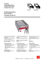
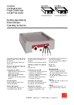
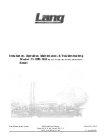
Installation of the appliance in a line
To fix the appliance in a line (neighbouring) follow
the steps:
Dismantle the control panel, and remove the cast
iron frame from the chimney if necessary.
Apply the sealing tape (
A
) onto the joining sides.
Place the appliances next to each other and in a
horizontal position (by adjusting the feet).
Connect the appliances with the joining elements.
8.6.
Modification for other type of gas (service technician)
The
device
has
been
checked
by
the
manufacturer for the type of gas shown on the
rating plate. If a different type of gas is used,
follow these instructions.
1.
Close the gas valve (
A
).
2.
Replace the burner nozzle (see chapter 9.3).
3.
Replace the nozzle of the ignition flame
(see chapter 9.5).
4.
Set a minimum value on the burner gas control
knob (see chapter 9.1).
5.
Remove the sticker from the rating plate and
apply a new sticker which includes the used
gas type (item 4 of the rating plate).
8.7.
Inspection (service technician)
Before starting the device, the installation check-
up should be run to evaluate the working
conditions of every single component and identify
any errors.
It is recommended to run the following check-ups:
1.
Open the gas valve and check the tightness of
connections;
2.
Check whether the igniter starts and burns
properly.
3.
Check and adjust, if necessary, the gas
pressure and flow rate in Max and Min
positions (see chapter 9.1)
4.
Check whether the safety thermostat
operates properly.
5.
Check gas pipes for leakages.
ID 12
A
A
B
C
C