background image


11 

ENGLISH 

GB 


8.3. 

Gas connection (service technician) 


A  gas  connection  must  be  performed  in 
compliance with the applicable regulations. 

Before  connecting  the  appliance,  check  the 
technical data, type  of gas, working pressure and 
flow rate which are provided on the rating plate. 

The  installation  is  performed  by  connecting  the 
connection pipe of the appliance with a pipe of the 
gas distribution network. A shut-off valve must be 
installed on the connection to shut the gas supply 
off if necessary.  

If  there  are  significant  pressure  differences  in  the 
gas  supply  installation,  it  is  recommended  to 
install a pressure regulator. 

After the installation, check the gas connection for 
tightness. 


When  looking  for  gas  leaks  do 

not use the open flame! 


8.4. 

Extraction of fumes  

 
Installation  of  the  type  “A”  devices  does  not 
envisage connection to the fume exhaust system, 
but  to  the  appropriate  extraction  hood  which 
discharges the fumes to outside. 
 

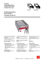
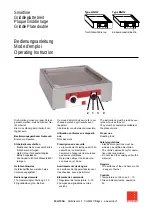
Installation under the extraction hood (A) 

Place  the  device  under  the  extraction  hood  (

1

and  attach  a  pipe  to  the  device  outlet  of  the  size 
as shown on the figures. 
 
The  end  of  the  fume  extraction  pipe  should  be 
located at least 1.8m above the floor. 


Gas supply of the device should 

be 

directly 

subjected 

to 

forced 

extraction  system:  blocking  of  the  fan 
must shut the gas supply off. 


The fan must switch on automa-

tically when the gas valve is open. 


ID 08 

Summary of Contents for FTG91MA1

Page 1: ...ING AND MAINTENANCE NSTRUCTIONS MANUEL D INSTALLATION D UTILISATION ET D ENTRETIEN MANUALE DI INSTALLAZIONE USO E MANUTENZIONE MANUAL DE INSTALACI N USO Y MANTENIMIENTO MANUAL DE INSTALA O UTILIZA O E...

Page 2: ...ODIFICATIONS TECHNIQUES CI RISERVIAMO LA POSSIBILIT DI INTRODURRE MODIFICHE TECNICHE SE RESERVA EL DERECHO A INTRODUCIR MODIFICACIONES T CNICAS SUJEITO A ALTERA ES T CNICAS TECHNISCHE WIJZIGINGEN VOOR...

Page 3: ...te 8 7 PROBLEMS DURING OPERATION 9 8 INSTALLATION 9 8 1 Packaging and unpacking 9 8 2 Installation service technician 10 8 3 Gas connection service technician 11 8 4 Extraction of fumes 11 8 5 Install...

Page 4: ...of the device 7 I Index plate 5 Inspection 12 Installation 10 Installation of anti splash cover 7 Installation of the appliance in a line 12 L Longer interval in the use of the device 7 M Maintenance...

Page 5: ...any other use is considered as the use not in compliance with the intended use The manufacturer is not liable for material damage or damage to person caused by misapplication or incorrect application...

Page 6: ...data Warning Indicate important safety instructions You should acquire the proper conduct to prevent hazard against people health and safety or not to cause any damage Caution Indicate essentials tech...

Page 7: ...to cool down 2 Open the door D 3 Press the safety thermostat button B to activate the gas supply again 4 Close the door D When using the devices with two griddle plates in order to detect the working...

Page 8: ...have altered the safety requirements 5 USE AND OPERATION 5 1 Description of the controls The elements controlling the essential functions are located on the control panel of the device A Gas control k...

Page 9: ...y clean the appliance and adjacent surfaces 3 Apply the vaseline oil on the stainless steel surfaces 4 Perform all maintenance works Guidelines on regular use of the device To guarantee the proper ope...

Page 10: ...n or plastic spatula or soft cleaning sponge to remove the dried remains If the appliance is not used for a prolonged time apply the Vaseline oil on all stainless steel parts and air the room regularl...

Page 11: ...burner and leave to dry off If the problem continues contact the customer service 8 INSTALLATION 8 1 Packaging and unpacking During unloading and when installing the device follow the information fro...

Page 12: ...alled with the minimum 5 cm clearance from the wall if the wall is not resistant to the minimum temperature of 150 C Locate the device in the horizontal position by adjusting the individual feet When...

Page 13: ...to install a pressure regulator After the installation check the gas connection for tightness When looking for gas leaks do not use the open flame 8 4 Extraction of fumes Installation of the type A de...

Page 14: ...he burner nozzle see chapter 9 3 3 Replace the nozzle of the ignition flame see chapter 9 5 4 Set a minimum value on the burner gas control knob see chapter 9 1 5 Remove the sticker from the rating pl...

Page 15: ...s pressure is compliant with the value of nominal pressure see table Follow these instructions 1 Close the gas valve 2 Remove the gas control knob A 3 Loosen the screws B and remove the control panel...

Page 16: ...ration and adjustment work check the gas installation for leakages and whether the device operates properly Make sure that the flame is stable at minimum and maximum output pressure After adjustments...

Page 17: ...see table in attachments 5 Finally set the device to the initial status 9 5 Replacement of the ignition flame nozzle Follow these instructions 1 Close the gas valve 2 Remove the gas control knob A 3...

Page 18: ...ual indicates that the product cannot be considered as ordinary household waste and should be transferred to a special collection point for electrical and electronic appliances for recycling Local was...

Page 19: ...I ANLAGEN ATTACHMENTS ANNEXES ALLEGATI ANEXOS ANEXOS BIJLAGEN ZA CZNIKI...

Page 20: ...Consumo gas Modelo Quemador Consumo de gas Modelo Queimador Consumo de g s Model Brander Gasverbruik Model Palnik Zu ycie gazu G20 G25 G30 G31 9 kW kW m h m h kg h kg h FTG91MA1 1 9 0 952 1 108 0 710...

Page 21: ...cordement du gaz Allacciamento gas Conexi n Gas Liga o de g s Gasaansluiting Przy cze gazu ANSCHLUSSSCHEMA CONNECTION CARD FICHE DES RACCORDEMENTS SCHEDA ALLACCIAMENTI FICHA DE ENLACES ESQUEMA DAS CON...

Page 22: ...EDA ALLACCIAMENTI FICHA DE ENLACES ESQUEMA DAS CONEX ES PLAN AANSLUITINGEN SCHEMAT POD CZENIA Gasanschluss R 1 2 UNI ISO 7 1 18 kW Gas Input Raccordement du gaz Allacciamento gas Conexi n Gas Liga o d...

Page 23: ...H3B P G30 G31 50 9 3 3 135 100 24 12 G20 20 9 3 3 230 140 24 12 CY II2H3 G30 G31 28 37 9 3 3 155 100 24 12 G20 20 9 3 3 230 140 24 12 II2H3B P G30 G31 30 9 3 3 155 100 24 12 G20 20 9 3 3 230 140 24 12...

Page 24: ...G31 30 9 3 3 155 100 24 12 G20 20 9 3 3 230 140 24 12 IE II2H3 G30 G31 28 37 9 3 3 155 100 24 12 G20 20 9 3 3 230 140 24 12 IS I3B P G30 G31 30 9 3 3 155 100 24 12 IT II2H3 G30 G31 28 37 9 3 3 155 10...

Page 25: ...100 24 12 G20 20 9 3 3 230 140 24 12 TR II2H3 G30 G31 28 37 9 3 3 155 100 24 12 G20 20 9 3 3 230 140 24 12 II2H3B P G30 G31 30 9 3 3 155 100 24 12 G20 20 9 3 3 230 140 24 12 Land Country Pays Paese Pa...

Page 26: ...alor calor fico mais baixo Onderste verbrandingswaarde Dolna warto opa owa MJ m3 Kcal m3 MJ m3 Kcal m3 MJ kg II G20 45 67 8129 34 02 G25 37 38 6989 29 25 III G30 80 58 10908 45 65 G31 70 69 11073 46 3...

Page 27: ...IX NOTE...

Page 28: ...QUESTO MANUALE CON DIVIETO DI RIPRODURLO E O DISTRIBUIRLO IN QUALSIASI FORMA SENZA NOSTRA AUTORIZZAZIONE DE ACUERDO CON LOS T RMINOS DE LA LEY EST RESERVADA LA PROPIEDAD DE ESTE MANUAL CON EXPRESA PRO...

Reviews: