background image


10 

ENGLISH 

GB 


8.2. 

Installation (service technician) 


All the stages of the installation must be carefully 
planned. 

The  location  should  be  equipped  with  all  supply 
connections  and  production  waste  outlet.  The 
location  should  also  be  properly  lit  and  comply 
with  all  hygiene  and  sanitary  requirements 
according to the binding regulations. 

The  device  should  be  installed  with  the  minimum 
10 cm clearance from the wall. 
Locate  the  device  in  the  horizontal  position  by 
adjusting the individual feet. 


The device FTE91 must be fixed to the foot flange 
at the bottom. 


When the device is to be installed 

near the walls, partitions, kitchen 
cabinets, decorative elements, etc., they 
must be made from non-flammable 
materials or covered with suitable non-
flammable materials.


To  ensure  the  correct  operation 

of  the  device,  the  device  must  be 
installed 

and 

operated 

in 

the 

thoroughly ventilated room only.


8.3. 

Connection to the mains (service technician) 


The device may be connected to the power supply 
only  by  the  authorized  and  qualified  personnel, 
when the valid regulations are followed and when 
appropriate  material  is  used  in  accordance  to  the 
regulations. 
 
Depending on the model the devices are designed 
for connection to the following networks: 

380-415 V 3N~ 50-60 Hz 

During the installation follow the data on the rating 
plate. 


Before connecting the device to 

the mains, check whether the device is 
connected to the appropriate circuit 
breaker in all poles with minimum air 
gap of 3 mm.


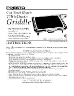
To  correctly  connect  the  device,  follow  the 
guidelines below. 
 

  Remove the cover from the terminal strip (A). 


10 mm 

Summary of Contents for FTE91MA0

Page 1: ...Rev Nr 01 2017 INSTALLATIONS BEDIENUNGS UND W ARTUNGSANW EISUNGEN INSTALLATION OPERATING AND MAINTENANCE NSTRUCTIONS MANUEL D INSTALLATION D UTILISATION ET D ENTRETIEN MANUALE DI INSTALLAZIONE USO E M...

Page 2: ...ODIFICATIONS TECHNIQUES CI RISERVIAMO LA POSSIBILIT DI INTRODURRE MODIFICHE TECNICHE SE RESERVA EL DERECHO A INTRODUCIR MODIFICACIONES T CNICAS SUJEITO A ALTERA ES T CNICAS TECHNISCHE WIJZIGINGEN VOOR...

Page 3: ...anti splash cover 7 5 4 Guidelines on how to use the device 7 6 CLEANING AND MAINTENANCE 8 6 1 Guidelines on cleaning and maintenance 8 6 2 Correct maintenance 8 6 3 Cleaning of the grill plate 8 7 PR...

Page 4: ...nts and accessories 5 Exchange of components 5 G General guidelines 4 Guidelines on cleaning 8 Guidelines on how to use the device 7 Guidelines on regular use of the device 7 I Index plate 5 Installat...

Page 5: ...other use is considered as the use not in compliance with the intended use The manufacturer is not liable for material damage or damage to person caused by misapplication or incorrect application of t...

Page 6: ...ve been used to stress important information or draw attention to essential data Warning Indicate important safety instructions You should acquire the proper conduct to prevent hazard against people h...

Page 7: ...for personal injury or damage to the components that arise due to application of other spare parts than original or intervention into the device without the manufacturer s consent that may have alter...

Page 8: ...ctive grease layer and any contaminants from the grill plate Heat the device to 200 C A Start the automatic switch off to turn on the electrical connection B Set the temperature controller A in desire...

Page 9: ...llow the instructions below 1 Turn on the automatic switch off to disconnect from the mains 2 Thoroughly clean the device and surrounding areas 3 Apply the vaseline oil on the stainless steel surfaces...

Page 10: ...all the stainless steel surfaces Do not use any clearing agents that contain substances hazardous or harmful to health solvents petrol etc At the end of the working day clean grill plate device Regula...

Page 11: ...ging avoid excessive incline When using the lifting equipment pay attention to the mains cable and feet position The packaging consists of the carton packaging and wooden pallet There are symbols prin...

Page 12: ...mable materials or covered with suitable non flammable materials To ensure the correct operation of the device the device must be installed and operated in the thoroughly ventilated room only 8 3 Conn...

Page 13: ...ed with the equipotential clamp M The terminal is marked with appropriate sticker 8 4 Installation of the appliance in a line To fix the appliance in a line neighboring follow the steps 1 Dismantle th...

Page 14: ...pliance is marked in conformity with the European Directive 2002 96 EG WASTE ELECTRICAL AND ELECTRONIC EQUIPMENT WEEE By disposing the appliance in accordance with the regulations the user contributes...

Page 15: ...ANLAGEN ATTACHMENTS ANNEXES ALLEGATI ANEXOS ANEXOS BIJLAGEN ZA CZNIKI...

Page 16: ...Peso Modelo Potencia Datos de instalaci n el ctrica Peso Modelo Pot ncia Dados para a instala o el trica Peso Model Vermogen Gegevens van de elektrische installatie Gewicht Model Moc Dane dot instala...

Page 17: ...roanschluss 7 5 kW Electric Connection Branchement Electrique Allacciamento Elettrico Conexi n el trica Liga o El trica Elektrische aansluiting Przy cze elektryczne ANSCHLUSSSCHEMA CONNECTION CARD FIC...

Page 18: ...Elektroanschluss 15 kW Electric Connection Branchement Electrique Allacciamento Elettrico Conexi n el trica Liga o El trica Elektrische aansluiting Przy cze elektryczne ANSCHLUSSSCHEMA CONNECTION CAR...

Page 19: ...M1 P4 P3 P2 P1 4 3 2 1 12 22 32 11 21 31 24 R3 R2 R1 B1 S1 LB LR 12 32 11 21 31 T1 22 LV M2 M2 M2 M1 1 12 22 32 11 21 31 24 R3 R2 R1 B1 S1 LB LR 12 32 11 21 31 T1 22 LV L1 L2 L3 N N M PE P4 P3 P2 P1...

Page 20: ...NOTE...

Page 21: ...NOTE...

Page 22: ...ESTO MANUALE CON DIVIETO DI RIPRODURLO E O DISTRIBUIRLO IN QUALSIASI FORMA SENZA NOSTRA AUTORIZZAZIONE DE ACUERDO CON LOS T RMINOS DE LA LEY EST RESERVADA LA PROPIEDAD DE ESTE MANUAL CON EXPRESA PROHI...

Reviews: