Pag. 27
Drainage connection
The drainage pipe must not be connected directly to a common drain, but positioned
over
a
reservoir, at a distance which does not allow it come into contact with the sides of the reservoir or
with the water inside it, in order to avoid contaminating the food in the tub.
Checking gas tightness and pressure (fig. 11 – pag. 5).
Before proceeding to check the pressure, it is necessary to check the tightness of the gas installation
up to the nozzle with a leak-finder spray to ensure that no damage has been done to the appliance
during transportation. Then it is possible to proceed with checking the inlet pressure, which is done
by means of a gauge for liquids , either a "U" gauge or an electronic gauge with a minimum
definition of 0,1 mbar. To carry out the reading, the screw (1) must be removed from the pressure
outlet (2) and the rubber pipe of the gauge connected. Open the gas supply valve of the appliance,
check the pressure output and close the valve. Remove the pipe of the gauge and put back the
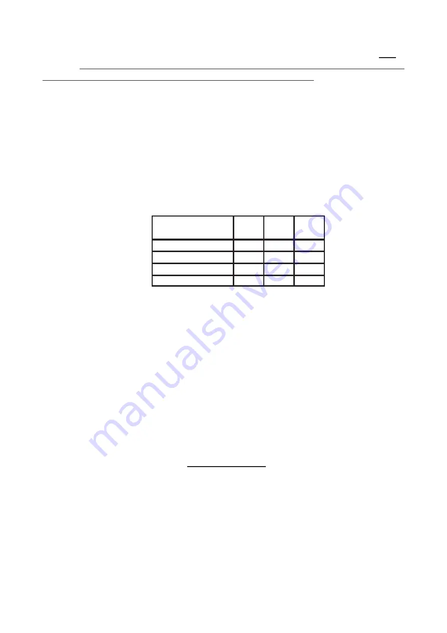
screws correctly into the pressure outlet. The pressure valve must be within the minimum and
maximum values shown below:
If the pressure reading is not within the limits of the table, find out the cause. After solving the
problem, check the pressure again.
Checking the power
Normally, it is sufficient to check that the nozzles installed are the right ones and that the burners
function properly. If desired, further check the power absorbed by using the "Volumetric Method".
With the help of a chronometer and a counter, it is possible to read the volume of gas output to the
appliance in time units. The right comparison volume [
E
] can be obtained with the formula shown
below in litres per hour (l/h) or in litres per minutes (l/min), by dividing the nominal and minimum
outputs (power) shown in the table of burner features for the lowest heat capacity of the type of gas
foreseen for use with the appliance. This value can be found in the norm tables or can be provided
by the local gas supply company.
The reading must be done when the appliance is already in function.
Checking pilot burner
Check the flame of the pilot burner, which must be neither too short nor too high but must lap the
thermocouple and have a sharp form; otherwise, it is necessary to check the size of the nozzle
depending on the pilot version, as specified in the following paragraphs.
Output (Power)
Heat Output
E =
Type of gas
P
n
[mbar]
P
min
[mbar]
P
MAX
[mbar]
G20 (Methane)
20
17
25
G25 (Methane)
25
20
30
G30 (Butane)
30
20
35
G31 (Propane)
37
25
45
Summary of Contents for 296.305
Page 44: ...CUOCIPASTA A GAS CUOCIPASTA ELETTRICI SERIE 900 MASTER INSTALLAZIONE USO E MANUTENZIONE I CH...
Page 57: ...57...
Page 58: ...58...
Page 59: ...59...
Page 60: ...60...
Page 61: ...61...
Page 64: ...Et E E KW d s d E E WW E W h s D D 64...
Page 65: ...Z s E s E WW Z d E Z s Z s sKKZ Z E s E E d d s s t dZ d Z dZ d s...
Page 66: ...s t s Z sh Z s E d s s Z s s Z t E...
Page 67: ...E d d s s ZE ZK E...
Page 68: ...s Yh WKd Ed t h t s s h K K W W WD y E...
Page 69: ...E D K KW d sKKZ E E D d E KKZd t d s E Z E d E t K E s...
Page 70: ...s 60 K E W 60 E s 60 K E s 60 K s s Zh Et E K...
Page 71: ...s W d W t s K KW d s Z KZ E E KE Z Kh s E d WW Z d Z KW d s Z D D K E...
Page 72: ...K KW d s s D K s Zs E E s E KE Z E KW d s s K E d K s s K D...
Page 75: ...75...
Page 76: ...76...
Page 77: ...77...
Page 78: ...78...
Page 79: ...79...
Page 82: ...t Mt W h h t E ht W h W h tB _ tK_ d E E W W d t t s D h Z...
Page 83: ...E KW hZ F K W K W WZ z KdKt E E d D h t W h s t dZ d Z dZ d Z W...
Page 84: ...s t D h t W t s t W sh E d t s W t W K W W E t K h h t t t t h W K W t W W...
Page 85: ...t t W E d W Z W t t W W W W t t W W W W E ZE MBdK KE K...
Page 86: ...D E K t W t W t W t d W W W W Z K W E K K t Z W W WD y W...
Page 87: ...t W W t t ht t h d t E tzD Ez t WZ zW h K D EE K ZK h h W t Z W W t D...
Page 88: ...t t W W Z W t W W W W W W t t W E dZh K Bh W W d...
Page 89: ...t t W W Z E E E K t W ht h W E KE Zt hZ E ht W W W E E d W...

