background image

18 


Timer/Mister Function 

Depending on whether you are in Timer mode or Mister mode, the timer settings screen will 

look different. By pressing the mode box, you can toggle between the two options. You have a total of 
two timer outputs, meaning that you could have one on timer mode and the other on mister mode, if 
desired. There is also an option to use the timer in combination with the alarm function for shade 
curtain control. 


Timer Mode 

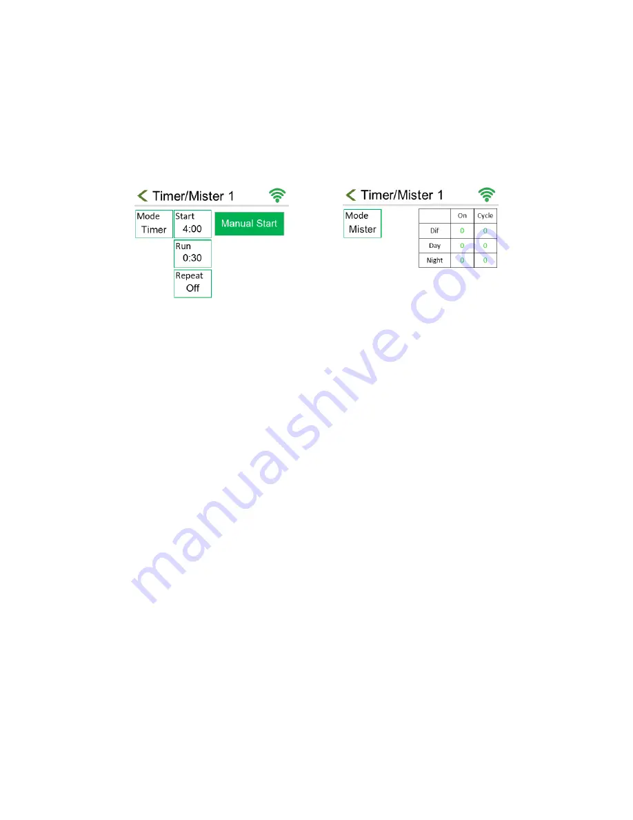
In timer mode (Figure 10), the timer relay will turn on at a single designated time of day and run 

for a set length, with the option to repeat daily. You can also manually start the timer whenever desired 
while in this mode, unlike mister mode. 

Start – To set when your timer will turn on during the day, press the start box like seen in Figure 
10.
 On the following screen, you can enter your start time. 

Run – To choose the run time press the run box, as seen in Figure 10. On the following screen, 
you can enter the duration of your run time in hours:minutes format. The maximum entry is 23 
hours and 59 minutes (23:59).  

Repeat – To choose whether it will repeat the following day, press the repeat box, like seen in 
Figure 10This will toggle between on and off. If set to off, the mode will return to the “off” 
state after the timer runs. 

Manual Control – Timers can also be manually started by pressing the green manual start 
button like seen in Figure 10. When a timer is running, this button can be used to turn it off. 

Mister Mode 

In the misting mode (Figure 11), the timer will come on for a number of seconds (the On-time) 

and will repeat after a number of minutes (the Cycle time). Each stage (DIF, DAY, NIGHT) has unique on 
and cycle times. To program them, simply press the value you want to change in the chart, as seen in 
Figure 11. Remember, the On-time refers to how long each timer will become active for in seconds. The 
Cycle time refers to how long each timer will wait before becoming active again in minutes.  

The cycle time will start counting when the output comes on. For instance, an on-time of 30 

seconds and cycle time of 1 minute, will have 30 seconds of on-time and 30 seconds of off time. 

Figure 10: Timer Settings


Figure 11: Mister Settings


Summary of Contents for ClimateBoss

Page 1: ...CLIMATEBOSS Controller Louver Fan GHK Mode Operation Manual BARTLETT Instrument Co 1032 Avenue H Fort Madison IA 52627 319 372 8366 www bartinst com...

Page 2: ...0 Vent C D Settings 10 Timer Mister 1 2 10 Dehumidify 11 Statistics 11 Settings 11 Configuration 12 Programming 14 Stages DIF DAY NIGHT 14 Outputs Heat 1 Cool 1 14 Date Time 15 Dehumidification Vent C...

Page 3: ...ter COOL 1 to allow louvers to open In two zone mode COOL 2 and COOL 4 will not activate for 30 seconds after COOL 1 and COOL 3 respectively Definitions First we need to define and understand some ter...

Page 4: ...nly displays when Auxiliary options C or CH are enabled Press to change settings Current Stage Displays the controller s current stage DIF DAY or NITE Graph Button Press to view graph of the controlle...

Page 5: ...p to change settings Outside Weather Displays current temperature outside Tap to view status and settings of Wind Rain alarm if connected Timers Timer outputs used for lights irrigation or other equip...

Page 6: ...erature for each stage and 24hr period Helps with troubleshooting and graphical tracking Timer Mister output for lights or irrigation fogging Humidity probe input to trigger the dehumidification vent...

Page 7: ...u to lower the temperature at night to save on heating Controller Operations Target Temperature The figure below explains the workings of the stages DIF DAY and NIGHT Figure 4 shows the controller pro...

Page 8: ...to the target temperature for each output Controller Operations Output Temperature Using the information in Figure 4 Figure 5 if the time is 8 00 AM the operating stage is DIF and the target temperatu...

Page 9: ...iances but will also give a wider swing in temperature The hysteresis can be set to values of 1 2 or 3 through the menu options Using the output temperatures from Table 1 and a hysteresis setting of 1...

Page 10: ...mes on based on their offset Each output has an offset or step temperature to be added to Cools or subtracted from Heats the set point to determine when each output will activate As the controller cha...

Page 11: ...e the last reset Settings Zone 1 Low Alarm Used to set the temperature for Zone 1 low alarm Default 32 F Zone 1 High Alarm Used to set the temperature for Zone 1 high alarm Default 131 F Zone 2 Low Al...

Page 12: ...s used in conjunction with the Headgrower mobile app for remote monitoring and control of the Climate Boss See the WiFi section for more information about firmware updates WiFi Set up Wi Fi for Firmwa...

Page 13: ...parate sensor thermistor for controlling boilers or bench heat Option CH combines Option C Option H to add both a proportional Curtain Vent control and a 3rd Heat option Timer Alarm Shade The Timer an...

Page 14: ...ext screen then press save To edit a temperature follow the same steps except under the zone1 or zone2 column entering your desired temperature on the next screen You can see the timeline of your sett...

Page 15: ...btracting your step value see Table 1 on page 8 Therefore you edit this value by changing the step value seen below SP To change your offset value press the green number in the SP row Enter your value...

Page 16: ...r high You can change it to use a custom value by pressing the checkbox next to set temperature and entering a value The limits can only be set between the values of 32 and 131 Stage Enable Choose wha...

Page 17: ...are in Timed mode Press it to toggle between on and off If on the vent cycle will continue to activate at its start time every day If off the vent cycle will activate at its start time a single time b...

Page 18: ...utes format The maximum entry is 23 hours and 59 minutes 23 59 Repeat To choose whether it will repeat the following day press the repeat box like seen in Figure 10 This will toggle between on and off...

Page 19: ...rtain opens and the run time will determine how long it stays open At the end of the timer the alarm will activate sending a message to CIS that you can ignore and closing your curtain shade Curtain V...

Page 20: ...tep before the curtain vent will open or close to the next setting Tap this box to enter a value between 1 and 9 minutes Open Time You ll need to manually measure the amount of time in seconds to manu...

Page 21: ...e mid right of the screen See figure 15 The Heat 3 output is currently active if the box surrounding Heat 3 is red Grey indicates inactivity Wind Rain Alarm Integration If your operation has both our...

Page 22: ...ler s home screen The ClimateBoss also tracks the run time of each of the outputs Heat 1 Heat 2 Cool 1 Cool 2 Cool 3 Cool 4 and Heat 3 H and CH versions The ClimateBoss will store the information unti...

Page 23: ...set point see Stages page 13 during the next stage transition DIF DAY NIGHT Vent Cycle or Timer Manual Start The dehumidification vent cycle or a timer cycle can be manually started This allows you to...

Page 24: ...mum setting of 55 Minimum setting of 1 DAY target temperature 18 Maximum setting of 55 Minimum setting of 1 NITE target temperature 18 Maximum setting of 55 Minimum setting of 1 Hysteresis setting 1 N...

Page 25: ...N SETTING Temperature Speed Units Fahrenheit F mph CIS ID 1 On to Auto time 10 Heat Cool Delay 15 Hysteresis 1 cannot be changed Alarms both zones Low 32 F High 131 F Number of Zones 1 Thermistor Fail...

Page 26: ...ed when the calibration code is requested below The calibration code is also located on the label inside the humidity sensor casing To change enter your calibration code go to Menu Configuration Humid...

Reviews: