background image

1

2

1

2

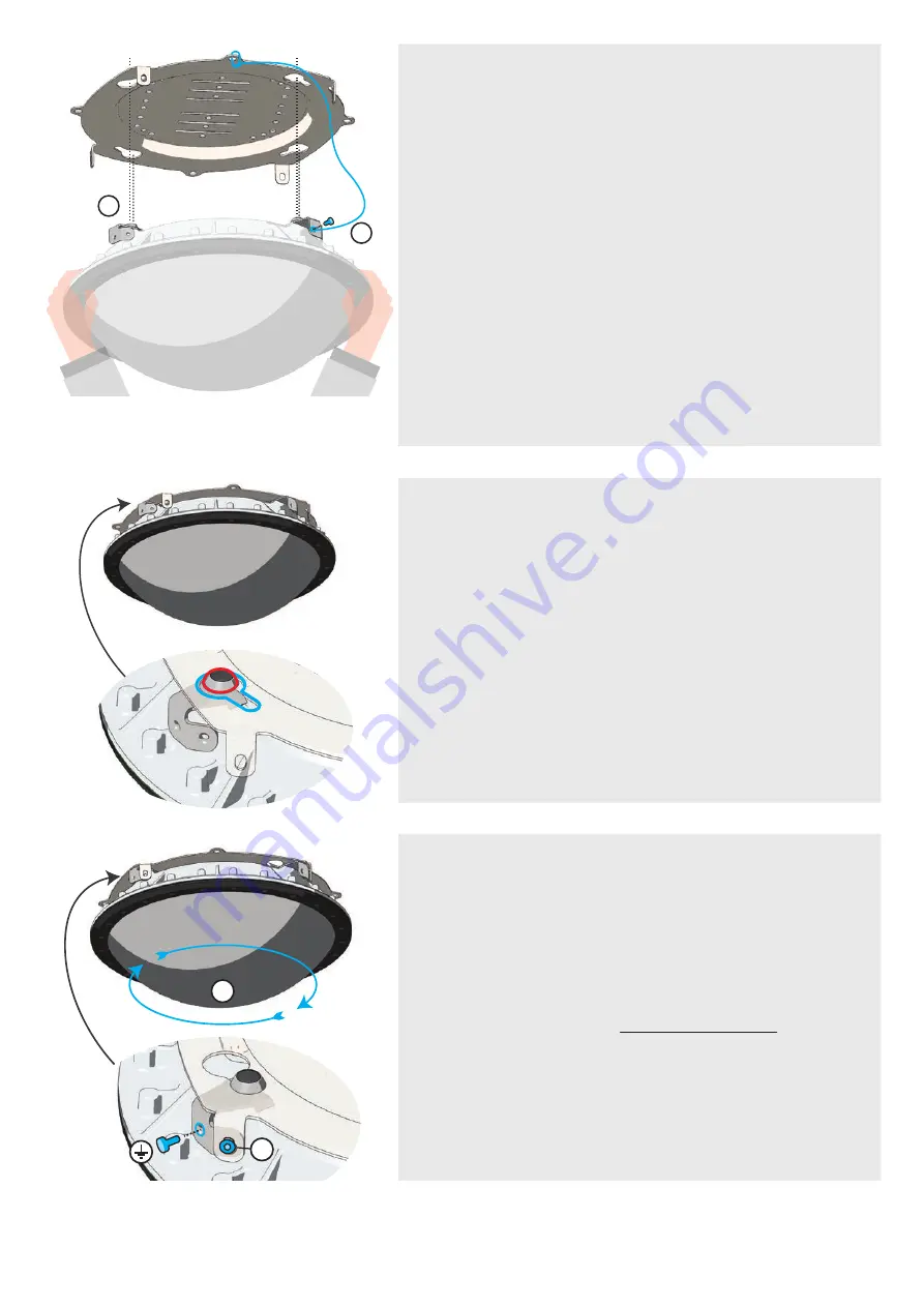
Mount ceiling bracket

Attach Wireless X

Fixing and earthing

1)

 Make sure the bracket is securely fixed to the 

cealing.  Attach  the  safety  wire  to  the  Wireless  X 
using a M6 fastener and then attach the other end 
of the safety wire to the ceiling bracket. The safety 
wire  is  not  meant  for  carrying  the  entire  weight 
of  the  Wireless  X  during  installation.  It's  solely  a 
safety measure to avoid the Wireless X from drop 
to the ground in case of an accident.  

2)

 Lift and align the Wireless X towards the ceiling 

bracket. 

Attach the Wireless X to the ceiling bracket. Make 
sure the feet enter the slots in the bracket.

1)

 Rotate the Wireless X clockwise to lock it to the 

bracket.

2)

  Fix  the  Wireless  X  to  the  ceiling  bracket  with 

M6 fasteners. At least 

two different tabs

 must be 

used.

The unused fixing points may be used for earthing. 
For additional earthing info, see page: 19.

1.

2.

3.

27

Installation

Summary of Contents for Wireless X BPXWXU1

Page 1: ...User Manual English BPXWXU1 revision 4...

Page 2: ...isy chain configurations DSY 18 Fiber daisy chain FIB DSY 18 Power daisy chain PWR ETH DSY 19 Preparations before installing 20 Ceiling bracket 21 Wall bracket 22 Pipe bracket Horizontal 23 Pipe brack...

Page 3: ...d our FAQ page for troubleshooting advice and directions on running hardware diagnostics 2 Consult the user manual which is included in your order If you need additional assistance please use one of t...

Page 4: ...ng solution for wireless equipment ever created for hazardous areas Based on both clever engineering material science and state of the art wireless infrastructure we are now eliminating the need for b...

Page 5: ...on dependent Power supply RF transparent dome PRODUCT OVERVIEW Input output glands Input output Ex d bushing Input output Ex d bushing Bracket for earthing and locking Ex e enclosure Ex d enclosure Te...

Page 6: ...X Mfr BARTEC GmbH 97980 Bad Mergentheim DE 85 264 VAC 47 63 Hz 120 370 VDC Max 10 A II 2G 0044 Markings Explained Wireless radio enclosure Product type Ex db eb IIC T6 Gb Ex Denotes explosive atmosph...

Page 7: ...not influence explosion protection ID number for additional cable options STN No additional option DSY Daisy chain Introduction Special Conditions for Safe Use X The instruction indicates all the nece...

Page 8: ...sharp objects like scissors or knives when opening the box This may damage the content Wireless X Mounting bracket User manual Mounting hardware Mounting fixture Wireless X enclosure Stainless steel m...

Page 9: ...se in potentially explosive atmosphere should be done in accordance with IEC EN 60079 14 17 19 Product installation must be carried out in accordance with any local codes that may apply and should onl...

Page 10: ...o splice accordingly Prepare the fiber Strip the protective coatings jackets tubes strength members etc leaving only the bare fiber showing Make sure that fiber surface area is clean Splicing fiber Al...

Page 11: ...one gel and or mechanical crimp protectors will keep the splice protected from outside elements and breakage Protection of the splice 6 7 Connect power and ground Verify that the incoming powercable i...

Page 12: ...ium strength thread locking sealant on all the 7 fasteners 1 Remove Ex e lid and insert cables into glands Unscrew the 7 M6x1 fasteners and remove the Ex e lid to access the power and network interfac...

Page 13: ...on points are spring loaded Important Follow the color coding indicated in the illustration to the right Terminate Ethernet cable 5 6 Add cable ferrules Connect ground cable to the earth terminal For...

Page 14: ...uctions of the cable glands thoroughly 3 Cut cable insulation and ethernet shielding according to the illustrated values and add cable ferrules Place the Ethernet cable shield in contact with the shie...

Page 15: ...e lid 5 Connect power and ground Verify that the incoming power cable is NOT live using a multimeter Add cable ferrules Connect power and ground cables to the power and earth terminals For additional...

Page 16: ...mounting instructions of the cable glands thoroughly 3 Verify that the incoming power cable is NOT live using a multimeter Connect power and ground cables to the power and earth terminals For additio...

Page 17: ...A3 Andreas G Mysen 07 Nov 17 47 92 26 92 64 01 External earth 4 possible locations provided and installed by customer Minimum 4mm2 cable M6 ring terminal M6 stainless steel locking washer M6 x1 0 stai...

Page 18: ...ber cable in the fiber splice tray and feed it out of the gland Positioning the fiber cable FIBER DAISY CHAIN FIB DSY 1 Overview Make sure the fiber and power are terminated as explained in FIBER VERS...

Page 19: ...Termination POWER DAISY CHAIN PWR ETH DSY 1 Overview Make sure the power cables are terminated as explained in POWER VERSION PWR or ETHERNET AND POWER VERSION ETH Insert an extra gland for the daisy c...

Page 20: ...t the measures that must be taken to ensure people are not at risk of falling from height PREPARATIONS BEFORE INSTALLING General info It s recommended to do a site survey to determine the best locatio...

Page 21: ...e high quality mounting hardware recommended for the mounting structure 1 Installation 200 176 5 150 250 mm 200 176 5 150 Prefered mounting holes 9 Alternative mounting holes 9 Only mount the Wireless...

Page 22: ...Attach wall bracket Mount to structure Secure the wall bracket to the ceiling bracket with the bolts washers and nuts supplied Mount the bracket using the recommended mounting points Only use high qu...

Page 23: ...e First check the diameter of the pipe pole Insert the pipe bracket into the slots according to the pipe diameter Secure the pipe bracket to the ceiling bracket with the bolts washers and nuts supplie...

Page 24: ...WALL is needed to ensure the dome is facing downwards The pipe brackets would then need to be mounted on the wall bracket The wall bracket can be mounted in different angles to fit different pipe pole...

Page 25: ...the wall bracket Make sure they are in the correct position Secure the pipe bracket to the wall bracket with the bolts and nuts supplied Mount the bracket assembly to the structure using the supplied...

Page 26: ...d earthing Safety wire Hole for Wireless X enclosure Tab for locking M6 fastener Ensure that the Cabling and termination step is finished before mounting the device to the bracket Ensure that the moun...

Page 27: ...installation It s solely a safety measure to avoid the Wireless X from drop to the ground in case of an accident 2 Lift and align the Wireless X towards the ceiling bracket Attach the Wireless X to th...

Page 28: ...th non conductive materials must be avoided INSPECTION MAINTENANCE Maintenance and inspection of the Wireless X mounted in explosive atmosphere should be done in accordance with IEC EN 60079 17 BARTEC...

Page 29: ...ptimize the network coverage Always mount the Wireless X horizontally with the dome facing down towards the area you want Wi Fi coverage Select a central location or one where you use your Wi Fi enabl...

Page 30: ...server to verify that the Access Point is connected and has received an IP address Check the AP vendors documentation Implementation guidelines for further troubleshooting How can I verify that the Ac...

Page 31: ...nverter and power supply Dome Cemented joint Termination plate For PWR Fiber and Ethernet Ex e compartment O ring 3 Ex e glands Fixing earthing bracket M6 fasteners for Ex e lid 4 Ex d bushings 188 5...

Page 32: ...omposite Marine grade gelcoat Ex e lid Lid for Ex e chamber Marine grade aluminum Powder coated Ex e Gasket Gasket for Ex e chamber NBR CS 1 5mm ID 275mm Screws and mountingparts All fasteners and ext...

Page 33: ...nger Date of issue 03 01 2018 Declaration We BARTEC PIXAVI AS Vestre Svanholmen 24 4313 SANDNES Norway declare under our sole responsibility that the product BARTEC PIXAVI Wireless X Wireless Radio En...

Page 34: ...34 Vestre Svanholmen 24 Norway 4313 Sandnes Tel 47 51731515 sales bartec pixavi com www bartec pixavi com BARTEC PIXAVI 2018...

Reviews: