background image


12 / 34 

www.bartec-syscom.com 

Copyright © Bartec Syscom 2019 

2.2  Keyboard 

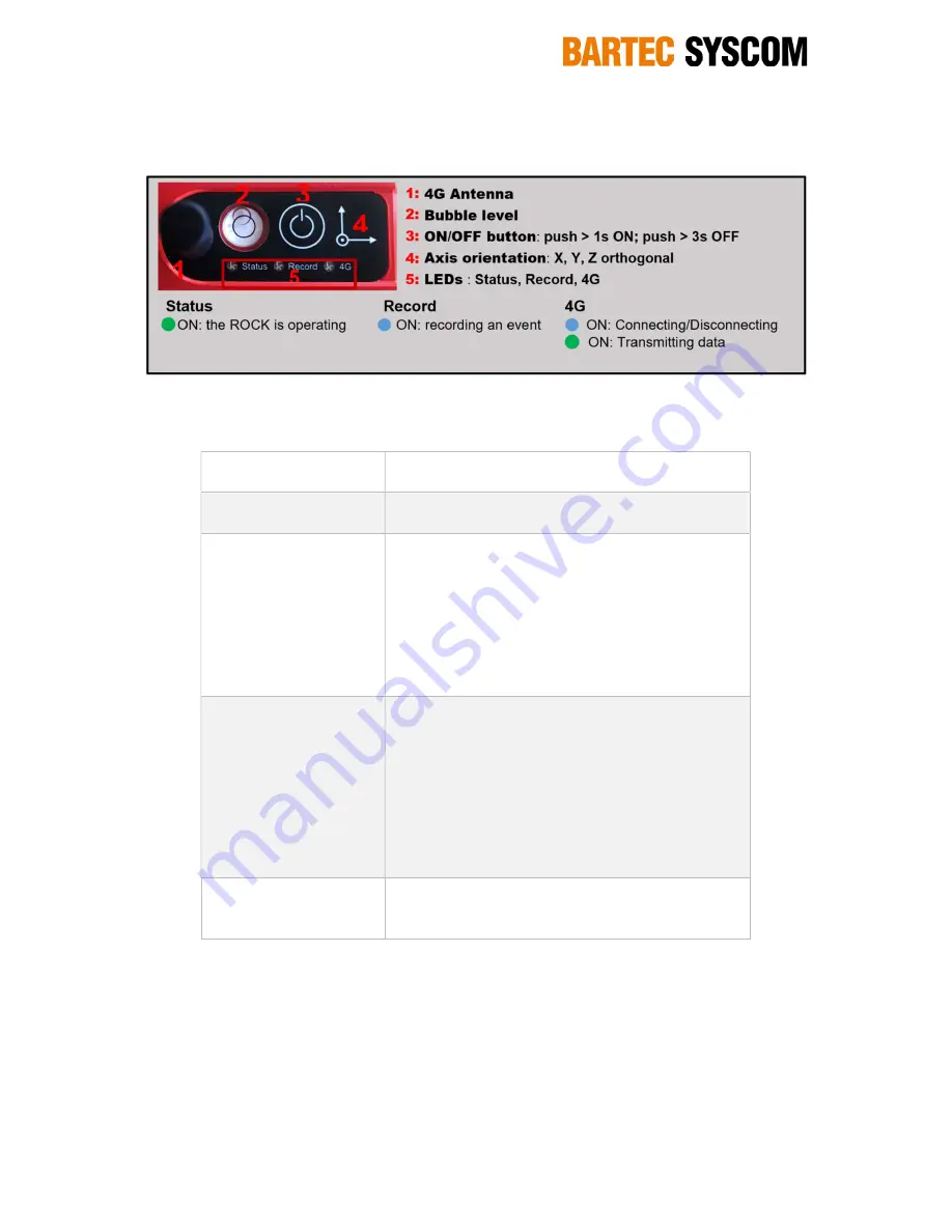
The general keyboard overview with LEDs colors and status are given in Figure 6 below. 


Figure 6: ROCK keyboard and LEDs status


The ON/OFF button has the following functions: 
 

SWITCH ON 

Push around 1s until the Status LED turns ON and 
release 

SWITCH OFF SW 

Push around 3s until the Status LED turns ON and 
release. The ROCK is turned OFF by the processor 

FIRMWARE UPGRADE 

Push around 10s until LEDs Status and Record are 
ON. This Set the Rock ready for firmware upgrade. 
With the ROCK connected to a computer using the 
ROCK USB cable, the ON/OFF button must be 
pushed until the LEDs Status and Record are 
permanently ON, copy the firmware file *.ava into the 
ROCK folder. The firmware upgrade starts 
automatically. 

DIAG REPORT 


Push around 20s until the 3 LEDs Status, Record and 
4G are ON. This generates a diagnostic report of the 
ROCK. The diag report can be downloaded using the 
USB cable and a computer. The diag report should 
be given to Syscom for evaluation. 

Important: Disconnect the USB cable from the 
ROCK once the diag report has been downloaded. 
Otherwise the ROCK will no longer be able to 
generate events 

SWITCH OFF HW 

Push around 30s. The ROCK will be turn OFF by the 
hardware. This can be used if the processor is 
crashed and need a reboot of the ROCK. 

 
It is recommended to install the ROCK at a proper location, level it and then switch it ON. Once 
switched ON and the ROCK is taking in a project and turn ON within the SCS plateform, the 
permanent monitoring starts automatically. 
ROCK device have to be setup using the SCS, refer to §3.4. 

2.3  Status LED 

Refer to Figure 6. 3 LEDs are available, giving important device conditions. 

Summary of Contents for SYSCOM ROCK

Page 1: ...t Bartec Syscom 2019 User Manual ROCK User manual V1 2 August 2019 bjt SYSCOM Instruments SA Rue de l Industrie 21 1450 Sainte Croix Switzerland Phone 41 24 455 44 11 support bartec syscom com www bar...

Page 2: ...2 1 3 Accessories 10 2 2 Keyboard 12 2 3 Status LED 12 2 4 Record LED 13 2 5 4G communication LED 13 2 6 Micro USB Connector 13 2 7 Battery Autonomy 14 2 8 Sensor Calibration 14 3 Syscom Cloud Softwar...

Page 3: ...2019 3 6 Notifications 25 4 Data visualisation 26 4 1 EVENT tab 26 4 2 BACKGROUND tab 27 5 Maintenance 28 6 Monitoring with the ROCK SCS 29 7 Safety instructions 30 7 1 Instructions 30 7 2 Declaration...

Page 4: ...ture of this monitoring solution Capabilities such as FTP data transfer ASCII file export and URL link sharing can be done in 1 click Typical non exhaustive applications are construction site monitori...

Page 5: ...process data the device will record and save the 3D vibration signals X Y Z axis referred as event only when a trigger level is exceeded After the recording the event is immediately pushed to the SCS...

Page 6: ...luation of the acquired vibrations Figure 2 Background recording 1 2 Specifications Mobile network Global 4G LTE multi band Cat M1 Nb IoT fallback 2G with eSIM Operating temperature 20 C up to 50 C Op...

Page 7: ...SNCF IN1226 o Germany DIN4150 2 DIN4150 3 o Italy UNI9916 o Norway NS8176 NS8141 o Portugal NP2074 o Spain UNE22 381 o Sweden SS 4604866 SS025211 SS4604861 o Switzerland SN640312a o The Netherland SB...

Page 8: ...4 www bartec syscom com Copyright Bartec Syscom 2019 2 Hardware 2 1 Mechanical overview 2 1 1 ROCK Main ROCK features Figure 3 ROCK general overview Refer to below chapters for more detailed informati...

Page 9: ...overall dimensions in mm Figure 4 ROCK dimensions in mm 2 1 2 ROCK SOLAR The solar panel for ROCK is suitable for outdoor usage Depending of the sunlight it may increase the autonomy of the device by...

Page 10: ...ssories Here are the main accessories for the ROCK devices Mounting plate with levelling screws 13100020 Wall mounting plate 1 fixation point 13100021 Carrying case for up to 4 ROCK 74710129 3 pointed...

Page 11: ...com com Copyright Bartec Syscom 2019 USB Charger USA plug without cable 87000318 USB charger 5V DC EU plug without cable 87000317 Remote LTE Cat M1 antenna with 2 m cable 87000321 Micro USB 1 8 meter...

Page 12: ...pgrade starts automatically DIAG REPORT Push around 20s until the 3 LEDs Status Record and 4G are ON This generates a diagnostic report of the ROCK The diag report can be downloaded using the USB cabl...

Page 13: ...g important device conditions 4G LED Blue LED Always ON Connecting disconnecting to the SCS Green LED Always on Connected to the SCS and transmitting the data OFF If the ROCK is active no synchronizat...

Page 14: ...vents per day of 15s automatically pushed to the SCS Background acquisition enabled peak ROCK SCS synchronization every 1 hours In order to extend the ROCK autonomy the ROCK solar can be used for outd...

Page 15: ...to be created in this tab to start a specific monitoring The project tab will also give access to all past and current monitoring o POOL this is where ROCK devices can be put into an SCS account assi...

Page 16: ...assword and follow the steps o Login again to an account is done using the following credentials username or Email and password 3 2 Pool management Once a Syscom local representative assign a ROCK to...

Page 17: ...LE POOL 3 3 Project management This PROJECT page allows to create add a project export the whole project archive or delete it Projects can also be accessed from here Figure 12 SCS Project management O...

Page 18: ...d state of health status to the SCS The following status are monitored o Last ROCK SCS synchronization time and date o Uptime of the device o Battery level with graph useful for preventive maintenance...

Page 19: ...sable Disabling trigger will also disable alarms based on trigger X or Y or Z axis trigger threshold must be set Threshold between 0 1mm s and 135mm s default 1mm s Pre event depending of the sampling...

Page 20: ...artec syscom com Copyright Bartec Syscom 2019 Refer to DIN 45669 1 standard for additional information on KBFTi mode Refer to SBR A Dutch standard for more information as well Figure 15 ROCK acquisiti...

Page 21: ...levels Alarm 1 enable disable Trigger based trigger mode enable Level DIN4150 3 SN640312a Circulaire du 23 07 1986 Arr t de 1994 BS5228 BS7385 2 NP2074 RI8057 OSMRE UNE 22 381 AS 2187 2 NORM S 9020 P...

Page 22: ...ation Rock SCS Synchronization to the SCS initiated by the ROCK every 5 to 1440 minutes 1day Default is 60 minutes 1h The background data will be pushed to the SCS at that time and the ROCK parameters...

Page 23: ...ast 1 device in the project should have a Trigger enable for Event reporting and a Background enable for periodic background reporting Event report if enable as soon as an event is uploaded to the SCS...

Page 24: ...ill automatically generate a PDF report based on the selected periodicity daily weekly monthly periods with all information using the active checkboxes in the below screen In case of notifications ref...

Page 25: ...H State Of Health If active the SCS will send Email SMS for the following state of health notifications o Test pulse fail o Low battery 10 autonomy remaining o Synchronization fail connectivity lost T...

Page 26: ...n a specific project will be classified in an Event table as displayed below Filtering options manual reporting and norm comparison data exporting and event visualization are easily performed Refer to...

Page 27: ...a continuous graphic The displayed period can be selected and the specific data points exported into an ASCII file to any third party software A reporting button related to the selected period is als...

Page 28: ...OCK adequately it is recommended to follow the below recommendations o Before installing the device at site internal battery should be fully charged o Installing ROCK on site should be done away from...

Page 29: ...rojects can be created D Setup the parameters of the devices the reporting and notifications in the SCS Note These configurations can be modified anytime in the SCS E Go to site and place the ROCK at...

Page 30: ...ased on European Union legislation shall be addressed to your authorized representative For any service or guarantee matters please refer to your representative or to the factory Notice for Wireless S...

Page 31: ...in locations environments or situations such as those listed below or the product may malfunction and cause a fire electrical shock damage and or injuries Location Do not place the product under wate...

Page 32: ...ies with separate collection systems This symbol indicates that the battery provided with this product shall not be treated as household waste By ensuring these batteries are disposed of correctly you...

Page 33: ...33 34 www bartec syscom com Copyright Bartec Syscom 2019 7 2 Declaration of conformity for ROCK device...

Page 34: ...ion RMA can be created here http www syscom ch services rma form Calibration centers can be found here http www syscom ch services calibration form Local Syscom representatives can be found here http...

Reviews: