background image

A Crane Co. Company

IMPORTANT! 

Read all instructions in this manual before operating pump.


As a result of Crane Pumps & Systems, Inc., constant product improvement program,


product changes may occur. As such Crane Pumps & Systems reserves the right to 


change product without prior written notifi cation.

420 Third Street   


83 West Drive, Bramton

Piqua, Ohio 45356-0603   

Ontario, Canada L6T 2J6

Phone: (937) 778-8947 


Phone: (905) 457-6223

Fax: (937) 773-7157 


Fax: (905) 457-2650

www.cranepumps.com

Form No. SM118049-Rev. B
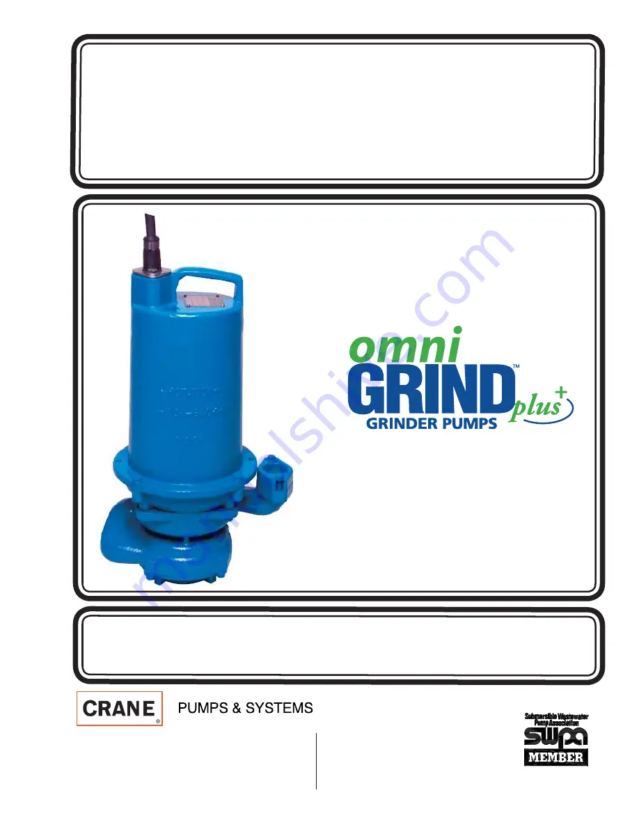
BARNES

BARNES

®

SERVICE MANUAL

OGP 2 HP Pump

Summary of Contents for OGP 2 HP

Page 1: ...roduct changes may occur As such Crane Pumps Systems reserves the right to change product without prior written noti cation 420 Third Street 83 West Drive Bramton Piqua Ohio 45356 0603 Ontario Canada...

Page 2: ...Removal 8 Suction Cover Removal 9 First Stage Impeller Removal 9 Volute 10 Oil Removal Pressure Check 11 Second Stage Impeller Removal 12 Shaft Seal 13 Motor Housing 14 15 Motor 16 Bearings 17 Station...

Page 3: ...p under pressure WARNING DO NOT wear loose clothing that may become entangled in the impeller or other moving parts WARNING Keep clear of suction and discharge openings DO NOT insert ngers in pump wit...

Page 4: ...rs 1 4 Nut Driver 1 8 Allen Wrench 5 16 Allen Wrench Needle Nose Pliers 4 PVC Coupler 1 4 20 Bolt Seal Pushers Part No TL 21356 Bullets Thread Protectors Part No TL 21375 Dielectric Cooling Oil 90oz B...

Page 5: ...5m or higher on all leads Note that a 0 reading indicates a dead short CAUTION After performing a megger test ALWAYS discharge cord set leads to ground Dielectric Withstand Test Hi Pot Test This test...

Page 6: ...wiring is faulty TABLE 1 Motor Winding Resistance MODEL No HP VOLT PH NEMA START CODE FULL LOAD AMPS LOCKED ROTOR AMPS CORD SIZE CORD TYPE CORD O D 02 5 in mm CORD LENGTH Ft m WINDING RESISTANCE MAIN...

Page 7: ...visual check from the face of the moveable to the lower pump bracket The face of the moveable needs to be parallel to the lower pump bracket When assembled on the pump the moveable face will be perpen...

Page 8: ...ing screw and washer The screw has green loctite so apply heat to the screw wedge a at blade screwdriver between cutter and shredding ring and remove screw Using a at punch and hammer tap the cutter i...

Page 9: ...olute First Stage Impeller Removal With the pump lying on its side use a hammer and tap on the face of the impeller vanes Then using a at punch and hammer tap the impeller in a counterclockwise direct...

Page 10: ...e two 5 16 bolts and at washers from the volute discharge Remove volute discharge ange and o ring Inspect cross over and discharge for signs of accumulation of solids and house hold items Also look fo...

Page 11: ...he terminal block to blow out To check the pump for any seal leaks attach the pressure gauge assembly using pipe sealant Tighten the tting into the hole Pressurize the gauge to 8 to 10 psi Use a soap...

Page 12: ...ed and some oil may seep from the motor housing Do not store this pump without the impeller in place to hold pressure on the seal spring Do not pressure check motor housing at this time Inspect spacer...

Page 13: ...shaft Examine all seal parts and especially contact faces Inspect seal for signs of wear such as uneven wear tracks on stationary members chips and scratches on either seal face DO NOT interchange se...

Page 14: ...motion Remove retaining snap ring with a medium at tip screwdriver Using a 1 4 20 bolt thread it into the center of the terminal block Pull straight up with a rocking motion to remove the terminal blo...

Page 15: ...ove 5 16 hex head bolts and lockwashers from motor housing and vertically lift motor housing from intermediate coupling Remove square ring from intermediate coupling 28 27 29 Inspect square ring for s...

Page 16: ...or CAUTION USE CARE NOT TO DAMAGE MOTOR WINDINGS WHEN REMOVING MOTOR STATOR Motor rotor and lower bearing can be removed from the seal plate by using an arbor press and lightly pressing on the wet end...

Page 17: ...removed from rotor shaft with a bearing puller NOTE Pictures below show bearing markings on outside of rotor When replacing bearings be careful not to damage the rotor or shaft threads Clean the shaft...

Page 18: ...18 Stationary Seal Remove the stationary seal from the seal plate by pressing out with a at tipped screwdriver Examine all seal parts and especially contact faces 37 36...

Page 19: ...aft applying force to the inner race of the bearing only Install top retaining ring on rotor shaft Using an arbor press hold the rotor and press the lower bearing on the rotor shaft apply force to the...

Page 20: ...with small amount of grease Set motor stator over rotor being sure that stator drops at against boss in coupling Place end bell on top of motor and insert the hex stator bolts in motor and torque to...

Page 21: ...21 Wiring Diagram Wiring Diagram For Emerson Electric Motor Wiring Diagram For Franklin Electric Motor Figure Figure D D Figure Figure E E...

Page 22: ...R ON THE SEAL PUSHER IT WILL DAMAGE THE SEAL FACE With seal guide over motor shaft lightly oil DO NOT grease guide shaft and inner surface of bellows on rotating seal With lapped surface of rotating m...

Page 23: ...ssembly onto motor shaft with machined step tting inside I D of seal spring by turning clockwise while holding shaft stationary with a screwdriver Tap impeller with a at punch and hammer in a clockwis...

Page 24: ...n groove in bottom seal plate Place volute on seal plate being careful not to damage square ring Place four 5 16 bolts and washers on and tighten equally to 11 ft lbs NOTE Volute discharge must line u...

Page 25: ...peller onto shaft by threading impeller clockwise until it stops against spacer sleeve Use a at punch and hammer to snug impeller against spacer sleeve Use a large screwdriver to hold shaft Suction Co...

Page 26: ...ver Radial cutter should be ush with shredding ring on suction side to within 020 Replace counter sunk washer and 1 4 allen screw and tighten to 6 5 ft lbs Use green loctite on threads CAUTION CUTTING...

Page 27: ...nd mount volute discharge ange with 5 16 hex head bolts and at washers NOTE Check the 1 1 4 NPT threads on the mounting ange and make sure they face the correct direction The chamfered side of the NPT...

Page 28: ...l if removed Use proper bolt to secure ground lug Place berglass sleeve over motor and ground leads if removed Pull wires through opening in top of motor housing while lowering motor housing onto seal...

Page 29: ...sure terminal block is engaged and install snap ring to retain terminal block Tighten bolts and lock washers into motor housing If there were optional pump features such as a oat re install those at t...

Page 30: ...30 Pin Placement Diagram Figure Figure F F Figure Figure G G Figure Figure H H SINGLE PHASE 240 VOLT AC SINGLE PHASE 240 VOLT AC AUF and AUE SERIES Wiring Harness Wiring Harness...

Page 31: ...tach the pressure gauge assembly using pipe sealant Tighten the tting into the hole Pressurize the gauge to 8 to 10 psi Use a soap solution around the sealed areas and inspect joints for air bubbles I...

Page 32: ...E Reference oil chart for suitable replacement oils SUPPLIER GRADE OUNCES BP Enerpar SE100 96 Conoco Pale Paraf n 22 96 Mobile D T E Oil Light 96 G G Oil Circulating 22 96 Imperial Oil Voltesso 35 96...

Page 33: ...33 OGP 2HP Exploded View Figure Figure K K...

Page 34: ...36391 Capacitor Run 27 1 099198 Capacitor Start 28 1 116658 Ball Bearing Upper Not Shown 29 1 116659 Ball Bearing Lower 30 1 or 2 625 02117 Sleeve 31 1 115327 Motor 2HP 240 Volt 1 Phase 32 1 103760 Te...

Page 35: ...35 Notes...

Page 36: ...CRANE PUMPS SYSTEMS INC 420 THIRD STREET PIQUA OHIO 45356 0603 U S A...

Reviews: