background image

F-3.2) Leak Checking - Double Seal:

When leak checking units, seal retainer (see Figure 3) should
be used in place of impeller and top cover (20) must be
removed. Push motor diaphragm (40) down into cavity. Place
a plug with no burrs or sharp edges (see Figure 4) in recess
formed by diaphragm. Hold diaphragm plug in place with
diaphragm clamp (see Figure 5) fastened to switch end bell.
Install approximately 4Ft. of 1/4" O.D. nylon tubing or
equivalent to inboard seal housing with a male connector
assembly. 

(NOTE: Run tubing thru drive end bell)

. Install

another compression fitting on opposite end of tubing so it can
be adapted to air line fittings. Install pipe plug (11) in either
switch end bell (42) or drive end bell (46). Apply 4 to 5 PSI air
pressure to nylon tubing attached to seal housing, submerge
motor, any bubbling indicates outboard seal leakage.


(NOTE: DO NOT APPLY HIGHER AIR PRESSURE TO
MOTOR OR SEAL HOUSING DUE TO THE POSSIBILITY OF
BLOWING SEAL SEATS OUT OF POSITION)

. Take motor

out of water and remove one pipe plug (11) from either end bell
(42 or 46) and apply 4 to 5 PSI air pressure. Hold tubing
attached to seal housing out of water and submerge motor.
Any bubbling indicates inbord seal leakage. In any case where
leakage occurs, changes must be made to correct the situation.
After removing motor from water, drain and dry all water from
top section of switch end bell.

F-3.3) Leak Checking - Leak Sensor:

Seal off hole for vent in bottom cover using a gasketed plate
bolted in place with 1/4-20 bolts and nuts. Remove vent plug
(82) and apply 4 to 5 PSI air pressure. Submerge unit in clear
water and check for air leakage. Release air pressure and
reinstall vent plug securely. Now, remove pipe plug (81) from
top cover (89) and apply 4 to 5 PSI air pressure. Submerge unit
and check for air leakage, correct any situation where leakage
occurs. See Section F-8 for assembly and disassembly.

F-4.1) Oil Filling - Pump:

(See Figures 4, 5, & 6).
All factory units are vacuum filled with dielectric oil (see Table
1). When vacuum filling these motors, use same diaphragm
retainer (see Figure 4) and clamp


(see Figure 5) as used when

leak checking. 

This plug will allow the diaphragm to partially raise up in cavity
when unit is being filled. This allows room for contraction of the
diaphragm when unit is operated in cooler temperatures.

COOLING OIL - Dielectric - TABLE 1

SUPPLIER

GRADE

BP

Enerpar SE100

CONOCO

Pale Paraffin 22

MOBIL

D.T.E. Oil Light

G & G OIL

Circulating 22

Imperial Oil

Voltesso-35

Shell Canada

Transformer-10

Texaco

Diala-Oil-AX

Woco

Premium 100

A 1/8" pipe nipple is attached to pipe plug opening in switch
end bell (42). A 1/2" or larger valve is attached to 1/8" nipple
with bushings. The unit is now turned upside down with shaft
up. A line (plastic tubing or pipe) is run from the valve into a
container of dielectric oil. A 1/8" pipe nipple is threaded into
pipe opening in drive end bell (46). 

A 3/8" nipple is attached to 1/8" nipple with bushings. A clear
plastic hose is connected to the 3/8" nipple. The hose is run up
vertically at least 3 ft. Now connect hose to vacuum source.
With the valve closed on the bottom side of motor,


25" to 29"

of vacuum is pulled on the motor. The valve under motor is now
slightly opened. Allow motor to fill with oil and oil level to rise
approximately 2" in plastic hose. Now close bottom valve. As
the air is pulled out of the unit, the oil level in the plastic hose
will drop. The valve to the oil must then be reopened to bring
the oil level up again. This may have to be repeated 2 or 3
times. After 10 to 15 minutes, the oil level in the plastic hose
should remain constant and no air bubbles should be flowing
up through the oil. Shaking the unit slightly will allow trapped
air to rise through the oil. If there are no air bubbles flowing up
through the oil, the unit is full. 

NOTE:

 If a steady stream of air

bubbles persists, there is a leak in the unit. Check all joints,
gaskets and seal.

Remove upper hose and fittings, insert pipe plug and secure.
Turn the unit right side up and fill the pipe that was connected
to the oil source with oil. Open the valve, then remove the pipe
and valve, insert pipe plug and secure. 

NOTE:

 Be sure motor

is completely filled. Reassemble per section F-7.

F-4.2) Oil Filling - Leak Sensor:

When leak testing is finished, make sure pipe and vent plugs
(81) and (82) are tight. (

NOTE:

 Vent plug must be in the closed

position). Now lay leak sensor on its side with hole in bottom
cover facing up, pour three (3) fluid ounces of cooling oil (see
Table 1) through hole in bottom cover. 

DO NOT OVERFILL

.

Leave leak sensor in a horizontal position until it is
reassembled to pump. Put O-ring (94) over tubing coming out
of pump. Hold finger over hole in leak sensor until it is aligned
with tubing. Bolt unit into place.

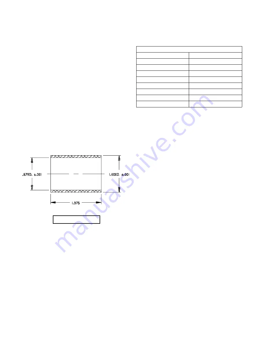
Fig. 3 - Double Seal

10

Summary of Contents for 4SE-EDS Series

Page 1: ...product changes may occur As such Crane Pumps Systems Inc reserves the right to change product without prior written notification SERIES 4SE EL 1 5 6 7HP 1750 RPM SERIES 4SE EDS 1 5 6 7HP 1750 RPM BA...

Page 2: ...CROSS SECTION Fig 21 22 4SE EDS EXPLODED VIEW Fig 22 23 4SE EDS PARTS LIST 24 25 4SE EDS LEAK SENSOR PARTS LIST 26 4SE EDS LEAK SENSOR EXPLODED VIEW Fig 23 27 START UP REPORT WARRANTY INFORMATION WARR...

Page 3: ...arge openings DO NOT insert fingers in pump with power connected Always wear eye protection when working on pumps Make sure lifting handles are securely fastened each time before lifting DO NOT operat...

Page 4: ...Phase NEMA B Three Phase Torque Curve Completely Oil Filled Squirrel Cage Induction Insulation Class A SINGLE PHASE Dual Voltage 200 230 Includes Overload Protection In Motor 1 5 2 2HP Capacitor Start...

Page 5: ...e Completely Oil Filled Squirrel Cage Induction Insulation Class A SINGLE PHASE Dual Voltage 200 230 Includes Overload Protection In Motor 1 5 2 2HP Capacitor Start 2 7 4 5HP Capacitor Start Capacitor...

Page 6: ...ly If it is required that the pump be installed and tested before the long term storage begins such installation will be allowed provided 1 The pump is not installed under water for more than one 1 mo...

Page 7: ...or cools to a safe temperature In the event of an overload the source of this condition should be determined and rectified immediately DO NOT LET THE PUMP CYCLE OR RUN IF AN OVERLOAD CONDITION OCCURS...

Page 8: ...Resistance 5 Start wires Black White Main wires Black Red Pump rated for operation at 10 Voltage at Motor MODEL NO A DIM HP VOLT PH NEMA START CODE FULL LOAD AMPS LOCKED ROTOR AMPS CORD SIZE CORD TYP...

Page 9: ...hould be taken to an authorized service station However as with any mechanical piece of equipment a preventive maintenance program is recommended and suggested to include the following checks 1 Inspec...

Page 10: ...rated in cooler temperatures COOLING OIL Dielectric TABLE 1 SUPPLIER GRADE BP Enerpar SE100 CONOCO Pale Paraffin 22 MOBIL D T E Oil Light G G OIL Circulating 22 Imperial Oil Voltesso 35 Shell Canada T...

Page 11: ...Fig 4 DIAPHRAGM PLUG Material 2 000 Dia Aluminum Fig 5 DIAPHRAGM CLAMP Material 750W x 375Thk Steel Fig 6 OIL FILLING 11...

Page 12: ...e stationary member is in straight Lightly oil shaft and inner surface of bellows on rotating member With lapped surface of rotating member facing inward toward stationary member slide rotating member...

Page 13: ...with hole in drive and bell Press housing in place and temporarily install two mounting bolts 67 Place several drops of oil inside of bellows of rotating member 13C and spread it over bellows Coat se...

Page 14: ...Y PRESSING ON INNER RACE Support rotor assembly on ring see Figure 13 when installing top bearing so that the pressing force is not transmitted through balls of drive end bearing Place Tetraseal 43 on...

Page 15: ...Fig 15 SINGLE PHASE 1 5HP 2 2HP Fig 16 SINGLE PHASE 2 7HP 4 5HP Fig 17 THREE PHASE 15...

Page 16: ...cord 83 to each electrode with screws at top of electrode holder 90 See Figure 18 After the leak sensor has been reassembled with all screws and threaded hardware thoroughly tightened it must be check...

Page 17: ...lean impeller cavity and inlet of any obstruction 9 Loosen union slightly to allow trappedair to escape Verify that turn off level of switch is set so that impeller cavity is always flooded Clean vent...

Page 18: ...Fig 19 SERIES 4SE EL 18...

Page 19: ...Fig 20 SERIES 4SE EL 19...

Page 20: ...2 Pipe Plug Hex Hd 1 8 Brass 017363 13 1 Shaft Seal C CE B 4023 14 8 Hex Hd Screw 1 4 20 x 1 00 Lg Stainless 1 7 1 15 16 Lock Washer 1 4 Stainless 20 13 1 16 2 RdHd Screw 10 32 x 375 Lg Stainless 2 8...

Page 21: ...460 3PH N4019 03 2 7HP 230 1PH N4019 09 2 7HP 230 460 3PH N4019 04 4 5HP 230 1PH N4019 10 4 5HP 230 460 3PH N4019 05 6 7HP 230 460 3PH N4019 11 48 1 Ball Bearing 039734 49 1 Ball Bearing 625 00719 50...

Page 22: ...SERIES 4SE EDS Fig 21 22...

Page 23: ...SERIES 4SE EDS Fig 22 23...

Page 24: ...Plug Hex Hd 1 8 Brass 017363 13 1 Dbl Mech Shaft Seal C CE B 007 00500 13A 1 Retainer 13B 1 Spring 13C 1 Seal Face 13D 1 Seal Seat 14 8 Hex Hd Screw 1 4 20 x 1 00 Lg Stainless 1 7 1 15 18 Lock Washer...

Page 25: ...ng Ring 625 00266 51 1 Shell 1 5 2 2HP 2 7HP 3PH 4005 01 2 7HP 1PH 4 5HP 6 7HP 4005 02 52 1 Stator 1 5HP 115V 1PH 625 00755 1 5HP 208 230 1PH 625 00753 1 5HP 208 230 3PH 625 00748 1 5HP 460 3PH 625 00...

Page 26: ...84 1 Thread Protector 4651 85 1 Packing Nut 3 4 16 4697 3 86 2 Flat Washer 007 00301 87 1 Grommet 007 00302 88 6 RdHd Screw 8 32 x 625 Lg Stainless 9 65 1 89 1 Top Cover 4690 102 90 1 Electrode Holde...

Page 27: ...SERIES 4SE EDS Fig 23 27...

Page 28: ...eld performance Any additional guarantees in the nature of performance specifications must be in writing and such writing must be signed by our authorized representative Due to inaccuracies in field t...

Page 29: ...ottom Does Impeller Turn Freely By Hand YES NO Condition Of Equipment GOOD FAIR POOR Condition Of Cable Jacket GOOD FAIR POOR Resistance of Cable Jacket GOOD FAIR POOR Resistance of Cable and Pump Mot...

Page 30: ...Pump Off L1 L2 L2 L3 L3 L1 Voltage supply at panel line connection Pump On L1 L2 L2 L3 L3 L1 Amperage Load connection Pump On L1 L2 L3 FINAL CHECK Is pump seated on discharge properly Check for leaks...

Page 31: ...Systems Inc Warranty Service Group IMPORTANT If you have a claim under the provision of the warranty contact your local Crane Pumps Systems Inc Distributor RETURNED GOODS RETURN OF MERCHANDISE REQUIRE...

Page 32: ...CRANE PUMPS SYSTEMS INC WARRANTY SERVICE GROUP 420 THIRD STREET P O BOX 603 PIQUA OHIO 45356 0603 U S A PLACE STAMP HERE FOLD HERE AND TAPE DO NOT STAPLE...

Reviews: