


12
Make sure the stationary member is in straight and that
the rubber ring is not out of it’s groove. Lightly oil
(DO NOT
use grease)
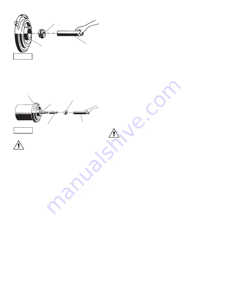
shaft and inner surface of bellows on rotating
member (10B) see Figure 8. With lapped surface facing
intermediate (2), slide rotating member (10B) onto shaft,
using seal pusher, until lapped faces of (10B) and (10A) are
together (see Figure 6).
IMPORTANT ! - It is extremely important to keep
seal faces clean during assembly. Dirt particles
lodged between these faces will cause the seal to
leak.
Place spring (10C) over shaft and in place on rotating
member (10B), making sure it is seated in retainer and not
cocked or resting on bellows tail. Slide retaining ring (10D)
over shaft and let rest on spring (10C). Assemble impeller
and volute as outlined in paragraph F-2.2.
Upper Seal- Clean and oil seal cavity in bearing bracket (3).
Lightly oil
(DO NOT use grease)
outer surface of stationary
member (9A), press stationary member (9A) fi rmly into
bearing bracket (3), using a seal pusher, nothing but the seal
pusher is to come in contact with seal face (see Figure 7).
Make sure the stationary member is in straight and that
the rubber ring is not out of it’s groove. Lightly oil
(DO NOT
use grease)
shaft and inner surface of bellows on rotating
member (9B) see Figure 7. With lapped surface facing
bearing bracket (3), slide rotating member (9B) onto shaft,
using seal pusher, until lapped faces of (9B) and (9A) are
together (see Figure 8). Place spring (9C) over shaft and
in place on rotating member (9B), making sure it is seated
in retainer and not cocked or resting on bellows tail. Slide
retaining ring (9D) over shaft and let rest on spring (9C),
replace snap ring (25) onto shaft. Assemble lower seal as
outlined and assemble impeller and volute as outlined in
paragraph F-2.2.
F-5) Motor and Bearing Service
F-5.1) Disassembly and Inspection:
To examine or replace the rotor (6), stator (7) and/or bearings
(11) and (12), drain oil from motor as outlined in paragraph F-
1.3, disassemble volute and impeller as outlined in paragraph
F-2, disassemble lower and upper seal as outlined in
paragraph F-4, disassemble junction box and cable assembly
as outlined in paragraph F-3.
Bearings- Slide motor, shaft and bearing bracket assembly
from motor housing (1). Examine upper bearing (12) and
replace if required. If replacement is required, remove bearing
(12) from motor shaft using a wheel puller. Remove snap ring
(8) or screws (19) with washers (20) from bearing bracket
(3) and remove bearing bracket (3). Now remove snap ring
(15) from shaft. Examine bearing (11) and replace if required.
If replacement is required, remove bearing (11) from motor
shaft using a wheel puller.
Motor- Inspect winding for shorts and resistance. To test
the temperature sensor, check for continuity between the
black and white wires. If found to be defective contact a
motor service station or Barnes Pumps service department.
Check rotor for wear. If rotor (6) or the stator (7) windings
are defective, the complete motor must be replaced. While
disassembled, check moisture sensor wires that they are
secured to the electrode (36).
IMPORTANT ! - All parts must be clean before
reassembly.
F-5.2) Reassembly:
Bearings - When replacing bearings, be careful not to
damage the rotor or shaft threads. Clean the shaft thoroughly.
On some models, fi rst slide bearing cap (4) onto shaft. Apply
adhesive compound to the shaft and press lower bearing (11)
on the motor shaft, position squarely onto the shaft applying
force to the inner race of the bearing only, until bearing seats
against shoulder of the shaft. replace snap rings (15) onto
shaft. Reassemble top bearing (12) in the same manner.
Motor- Slide lower bearing (11) and motor assembly into
the bearing bracket (3) until bearing seats on the bottom.
Position bearing cap (on some models) on bearing bracket,
insert screws (19) with washers (20) and tighten to 16 ft. lbs.
On other models insert snap ring (8) into bearing bracket
(3). Position motor and bearing assembly into pilot in motor
housing (1) while feeding motor leads through opening in
top of motor housing. Assemble upper seal as outlined in
paragraph F-4. Place o-ring (21) on motor housing (1). Place
intermediate (2) onto motor housing (1), being careful not
to damage o-ring, Insert screws (17) with washers (18) and
tighten. Assemble lower seal as outlined in paragraph F-4.
Assemble volute and impeller as outlined in paragraph F-2,
Assemble junction box and cable assembly as outlined in
paragraph F-3. Fill with oil as outlined in paragraph F-1.
F-5.3) Adapter Ring:
To remove or replace adapter ring (56), remove socket head
screws (55), hex nuts (53) and washers (54). Reassemble in
reversed order.
Stationary Member (9A) or
(10A), Polished Face Out
Intermediate (2) or
Bearing Bracket (3)
Seal Pusher
FIGURE 7
Rotating Member (46D)
Bullet
Motor & Bearing Bracket
Seal Pusher
Stationary
FIGURE 8
Summary of Contents for 4SCC Series
Page 15: ...15 FIGURE 9 Pump Series 4SCC 4SCD 4SCE 4SCF 100 132 Mtr Frame...
Page 18: ...18 FIGURE 10 Pump Series 4SCF 180 Mtr Frame...
Page 25: ...Notes...
Page 26: ...Notes...


