background image

6

SECTION B: GENERAL INFORMATION

B-1) To the Purchaser:


Congratulations! You are the owner of one of the 

fi

 nest pumps 

on the market today. CP&S pumps are products engineered 
and manufactured of high quality components. Over one 
hundred years of pump building experience along with a 
continuing quality assurance program combine to produce a 
pump which will stand up to the toughest applications. This 
manual will provide helpful information concerning installation, 
maintenance, and proper service guidelines.

B-2) Receiving:


Upon receiving the pump, it should be inspected for damage 
or shortages. If damage has occurred, 

fi

 le a claim immediately 

with the company that delivered the pump. If the manual 
is removed from the packaging, do not lose or misplace.

B-3) Storage:
Short Term-

 CP&S Pumps are manufactured for ef

fi

 cient 

performance following short inoperative periods in storage. 
For best results, pumps can be retained in storage, as factory 
assembled, in a dry atmosphere with constant temperatures 
for up to six (6) months. Long Term- Any length of time 
exceeding six (6) months, but not more than twenty-four (24) 
months. The unit should be stored in a temperature controlled 
area, a roofed over walled enclosure that provides protection 
from the elements (rain, snow, wind-blown dust, etc.), and 
whose temperature can be maintained b40 deg. F 
and +120 deg. F. (4.4 - 49°C). Pump should be stored in its 
original shipping container. On initial start up, rotate impeller 
by hand to assure seal and impeller rotate freely. If it is 
required that the pump be installed and tested before the long 
term storage begins, such installation will be allowed provided:

1.)  The pump is not installed under water for more than
 

one (1) month.

2.)  Immediately upon satisfactory completion of the test,
 

the pump is removed, thoroughly dried, repacked in the


original shipping container, and placed in a temperature


controlled storage area.

B-4) Service Centers:


For the location of the nearest Barnes Service Center, check 
your Barnes representative or Crane Pumps & Systems, Inc., 
Service Department in Piqua, Ohio, telephone (937) 778-8947 
or Crane Pumps & Systems Canada, in Brampton, Ontario, 
(905) 457-6223.

SECTION C: INSTALLATION

C-1) Location:


These pumping units are self-contained and are recommended 
for use in a sump, lift station or basin. The sump, lift station or 
basin shall be vented in accordance with local plumbing codes. 
This pump is designed to pump sewage, ef

fl

 uent, or other 

nonexplosive or noncorrosive wastewater. and shall 

NOT

 be 

installed in locations classi

fi

 ed as hazardous in accordance 

with the National Electrical Code (NEC), ANSI/NFPA 70 or the 
Canadian Electrical Code (CEC). Never install the pump in a 
trench, ditch or hole with a dirt bottom; the legs will sink into the 
dirt and the suction will become plugged. 

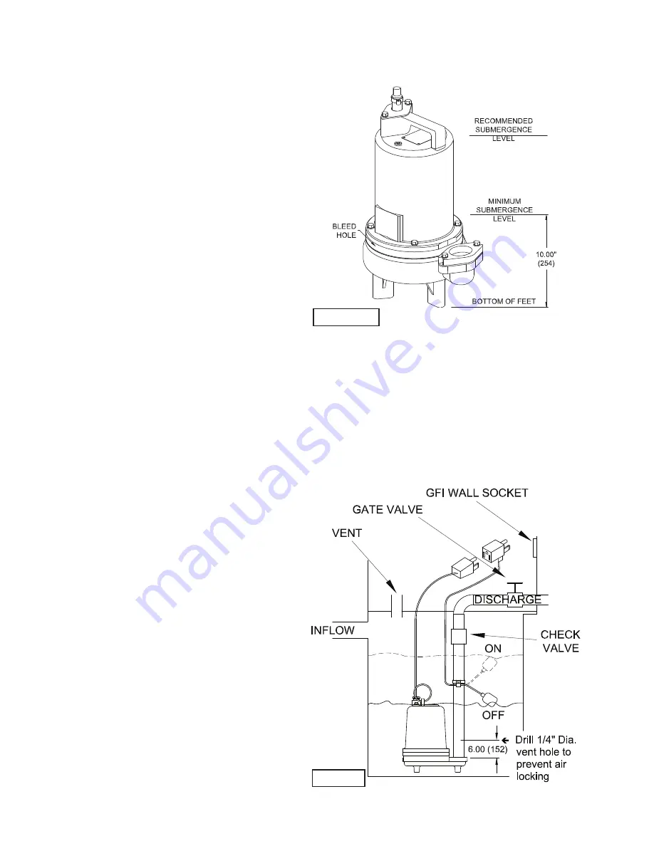
C-1.1) Submergence:

It is recommended that the pump be operated in the submerged 
condition and the sump liquid level should never be less than 
10 inches above the pump bottom (see Fig. 1).


C-2) Discharge:

Discharge piping should be as short as possible. Both a check 
valve and a shut-off valve are recommended for each pump 
being used. The check valve is used to prevent back

fl

 ow 

into the sump. Excessive back

fl

 ow can cause 

fl

 ooding 

and/or damage to the pump. The shut-off valve is used to 
stop system 

fl

 ow during pump or check valve servicing.

C-3) Liquid Level Controls:

Figure 2 shows a typical installation for any submersible pump 

using a level control mounted to the discharge piping with a 
piggy-back plug.

FIGURE 1

FIGURE 2

Summary of Contents for 3SF-L Series

Page 1: ...nstant product improvement program product changes may occur As such Crane Pumps Systems reserves the right to change product without prior written notification 420 Third Street 83 West Drive Bramton...

Page 2: ...PLODED VIEW Fig 16 15 PARTS LIST 16 17 RETURNED GOODS POLICY 12 WARRANTY 18 START UP REPORT 21 22 WARRANTY REGISTRATION SPECIAL TOOLS AND EQUIPMENT INSULATION TESTER MEGGER DIELECTRIC TESTER SEAL TOOL...

Page 3: ...rt fingers in pump with power connected Always wear eye protection when working on pumps Make sure lifting handles are securely fastened each time before lifting DO NOT operate pump without safety dev...

Page 4: ...1750 RPM 60Hz nominal UPPER BEARING Design Single Row Ball Oil Lubricated Load Radial LOWER BEARING Design Single Row Ball Oil Lubricated Load Radial Thrust MOTOR Design NEMA L Single phase Torque Cur...

Page 5: ...elief SPEED 1750 RPM 60Hz nominal UPPER BEARING Design Single Row Ball Oil Lubricated Load Radial LOWER BEARING Design Single Row Ball Oil Lubricated Load Radial Thrust MOTOR Design NEMA L Single phas...

Page 6: ...is not installed under water for more than one 1 month 2 Immediately upon satisfactory completion of the test the pump is removed thoroughly dried repacked in the original shipping container and place...

Page 7: ...e made in accordance with all applicord electric codes It is recommended that a junction box if used be mounted outside the sump or be of at least Nema 4 EEMAC 4 construction if located within the wet...

Page 8: ...be expected to operate for years on normal sewage pumping without failing However as with any mechanical piece of equipment a preventive maintenance program is recommended and suggested to include th...

Page 9: ...il Circulating 22 Imperial Oil Voltesso 35 Shell Canada Transformer 10 Texaco Diala Oil AX Woco Premium 100 F 2 Impeller and Volute Service F 2 1 Disassembly and Inspection To clean out volute 1 or re...

Page 10: ...ed or resting on bellows tail Slide retaining ring 28d over shaft and let rest on spring 28c Replace snap ring 32 in groove of shaft Set square ring 27 in groove on outer seal plate 29 and place outer...

Page 11: ...e bearing only until bearing seats against the retaining ring 24 Included with motor Motor Slide lower bearing 25 and motor shaft squarely into the seal plate 5 until bearing seats on the bottom Place...

Page 12: ...mation G 3 MODEL NUMBER This designation consists of numbers and letters which represent the discharge size series horsepower motor phase and voltage speed and pump design This number is used for orde...

Page 13: ...dom of operation security and condition Clean cutter and inlet of any obstruction 9 Loosen union slightly to allow trapped air to escape Verify that turn off level of switch is set so that the suction...

Page 14: ...14 FIGURE 15...

Page 15: ...15 FIGURE 16...

Page 16: ...g 24 1 085326 Retaining Ring Included with motor 25 1 017414 Bearing 26 4 1 135 1 Cap Screw 5 16 18 x 1 75 Lg Stainless 27 1 027269 Square Ring 28 1 Shaft Seal 005080 Carbon Ceramic Buna N 005080SB Tu...

Page 17: ...2 Discharge 3 8 Stainless 47 2 084948 Socket Head Cap Screw 1 4 20 x 1 25 Lg Stainless 60 A R Loctite 603 65 1 625 02117 Sleeve Fiberglass 66 1 030068 Jam Nut 20 S S TABLE 2 POWER CORD SETS CABLE LEN...

Page 18: ...PXVW EH VLJQHG E RXU DXWKRUL HG UHSUHVHQWDWLYH XH WR LQDFFXUDFLHV LQ HOG WHVWLQJ LI D FRQ LFW DULVHV EHWZHHQ WKH UHVXOWV RI HOG WHVWLQJ FRQGXFWHG E RU IRU XVHU DQG ODERUDWRU WHVWV FRUUHFWHG IRU HOG SH...

Page 19: ...nt To Insure That Employees Will Not Be Exposed To Health Hazards In Handling Said Material All Applicable Laws And Regulations Shall Apply IMPORTANT WARRANTY REGISTRATION Your product is covered by t...

Page 20: ...20 Notes...

Reviews: