


6
SECTION B: GENERAL INFORMATION
B-1) To the Purchaser:
Congratulations! You are the owner of one of the finest pumps
on the market today. CP&S pumps are products engineered
and manufactured of high quality components. Over one
hundred years of pump building experience along with a
continuing quality assurance program combine to produce a
pump which will stand up to the toughest applications. This
manual will provide helpful information concerning installation,
maintenance, and proper service guidelines.
B-2) Receiving:
Upon receiving the pump, it should be inspected for damage
or shortages. If damage has occurred, file a claim immediately
with the company that delivered the pump. If the manual
is removed from the packaging, do not lose or misplace.
B-3) Storage:
Short Term-
CP&S Pumps are manufactured for efficient
performance following short inoperative periods in storage.
For best results, pumps can be retained in storage, as factory
assembled, in a dry atmosphere with constant temperatures
for up to six (6) months. Long Term- Any length of time
exceeding six (6) months, but not more than twenty-four (24)
months. The unit should be stored in a temperature controlled
area, a roofed over walled enclosure that provides protection
from the elements (rain, snow, wind-blown dust, etc.), and
whose temperature can be maintained b40 deg. F
and +120 deg. F. (4.4 - 49°C). Pump should be stored in its
original shipping container. On initial start up, rotate impeller
by hand to assure seal and impeller rotate freely. If it is
required that the pump be installed and tested before the long
term storage begins, such installation will be allowed provided:
1.) The pump is not installed under water for more than
one (1) month.
2.) Immediately upon satisfactory completion of the test,
the pump is removed, thoroughly dried, repacked in the
original shipping container, and placed in a temperature
controlled storage area.
B-4) Service Centers:
For the location of the nearest Barnes Service Center, check
your Barnes representative or Crane Pumps & Systems, Inc.,
Service Department in Piqua, Ohio, telephone (937) 778-8947
or Crane Pumps & Systems Canada, in Brampton, Ontario,
(905) 457-6223.
SECTION C: INSTALLATION
C-1) Location:
These pumping units are self-contained and are recommended
for use in a sump, lift station or basin that is free of hard debris,
like gravel, stones, sand, or earth. The sump, lift station or
basin shall be vented in accordance with local plumbing codes.
This pump is designed to pump sewage, effluent, or other
nonexplosive or noncorrosive wastewater. and shall
NOT
be
installed in locations classified as hazardous in accordance
with the National Electrical Code (NEC), ANSI/NFPA 70 or the
Canadian Electrical Code (CEC). Never install the pump in a
trench, ditch or hole with gravel, stones, sand, or earth bottom;
the legs will sink into the dirt and the suction will become
plugged, or the pump impeller will be damaged.
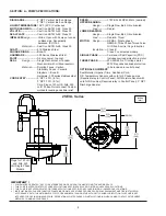
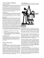
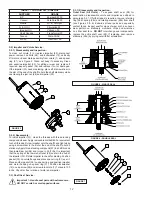
C-1.1) Submergence:
It is recommended that the pump be operated in the submerged
condition and the sump liquid level should never be lower than
the top of the pump (see Fig 2).
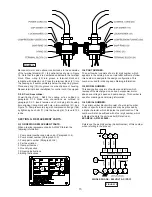
C-2) Discharge:
Discharge piping should be as short as possible. Both a check
valve and a shut-off valve are recommended for each pump
being used. The check valve is used to prevent backflow
into the sump. Excessive backflow can cause flooding
and/or damage to the pump. The shut-off valve is used to
stop system flow during pump or check valve servicing.
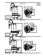
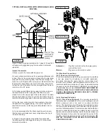
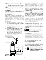
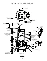
Barnes Pumps supplies a Stainless Rail Package for
the 2” models and also a variety of 2” and 3” break away
fitting discharge systems (see Fig. 1) designed to allow the
submersible wastewater pump to be installed or removed
without requiring personnel to enter the wet well. Contact your
local Barnes Pumps distributor for complete details.
Stainless Rail Package (Not Shown) - The package system
comes complete and ready to place into the ground as outlined
in the project specifications. The moveable portion of the Break
Away Fitting (BAF), check valve, piping and guide bracket
comes assembled on the pump along with the lifting cord.
Insert pump bracket and moveable portion of BAF into the
guide channel and lower pump into basin
(DO NOT DROP)
.
Now connect power and control cords to the junction box or
control panel depending on system design.
C-3) Liquid Level Controls:
The level controls are to be supported by a mounting bracket that
is attached to the sump wall, cover or junction box. Cord grips
are used to hold the cords in place on the mounting bracket.
The control level can be changed by loosening the grip and
adjusting the cord length as per the plans and specifications.
Be certain that the level controls cannot hang up or foul in it’s
swing and that the pump is completely submerged when the
level control is in the “Off” mode.
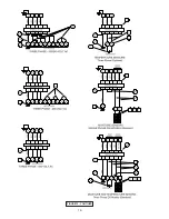
FIGURE 1
Summary of Contents for 2SEV-DS Series
Page 16: ...16 FIGURE 15 CONTIUED...
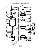
Page 18: ...18 FIGURE 16 2SEV L 3SEV L Series Single Seal...
Page 19: ...19 FIGURE 17 2SEV L 3SEV L Series Single Seal...
Page 20: ...20 FIGURE 18 2SEV DS 3SEV DS Series Double Seal...
Page 21: ...21 FIGURE 19 2SEV DS 3SEV DS Series Double Seal...
Page 25: ...25 Notes...
Page 26: ...26 Notes...


