


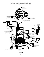


14
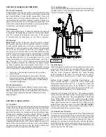
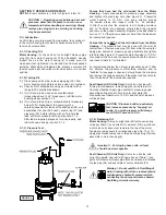
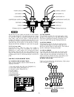
Position unit upright, using blocks to avoid resting unit on
shaft. Unscrew cord hex bolts (11) and remove compression
flange (16a) and power cord (16). Remove snap ring (19) with
a flat head screwdriver. Pull the terminal block (21) out of the
housing (6) using a T-bolt or a pair of pliers and a .25-20 screw
in the threads of the terminal block (21). Be sure to leave
slack on the motor leads connected underneath. Use needle
nose pliers to pull each female connector off of the pins on the
underside of the terminal block (21), see Figure 10. The unit
voltage should be noted.
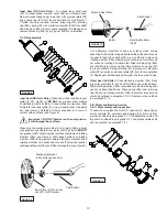
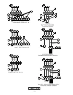
Repeat cord and terminal block removal procedure for any
control cords (56) if equipped. Remove socket head screws
(47). Vertically lift the motor housing (6) from seal plate (5)
by lifting handle (13). Inspect square ring (27) for damage or
cuts. Remove the motor bolts and lift motor stator from seal
plate (5). Disconnect capacitor leads from capacitor (9, single
phase units). Examine bearing (25) and replace if required. If
replacement is required, remove bearing (25) from motor shaft
using a wheel puller or arbor press, see Figure 11.
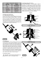
Check motor capacitor (9, single phase units) with an Ohm
meter by first grounding the capacitor by placing a screwdriver
across both terminals and then removing screwdriver. Connect
Ohm meter (set on high scale) to terminals. If needle moves
to infinity (∞) then drifts back, the capacitor is good. If needle
does not move or moves to infinity (∞) and does not drift back,
replace capacitor (9).
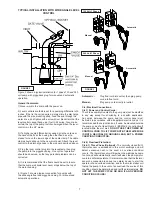
If moisture sensors (4, optional) are damaged, disconnect
leads by removing machine screws (45) and washers (46)
from probes (4). Remove probes (4) from seal plate (5). To
test the temperature sensor (50, optional), check for continuity
between the black and white wires. If found to be defective,
contact a motor service station or Barnes Pumps Service
department. Inspect motor winding for shorts and check
resistance values. Check rotor for wear. If rotor or the stator
windings are defective, the complete motor must be replaced.
Important ! - All parts must be clean before
reassembly.
F-4.2) Reassembly:
Moisture Sensors, DS Models -
If pump is equipped with
optional moisture sensors, reassemble by applying thread
compound to threads on probes (4) and install in upper seal
plate (5), see Figures 17 and 18. Connect wire assemblies
(53) to probes (4) with washers (46) and machine screws (45).
Thermal Sensors-
If pump is equipped with optional thermal
sensors use terminal connectors (52) to connect wire
assemblies (51) to sensor leads. If found to be defective, contact
a motor service station or Barnes Pumps Service department.
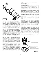
Bearings-
When replacing bearing, be careful not to damage
the rotor or shaft threads. Clean the shaft thoroughly. Press
bearing (25) on the motor shaft, position squarely onto the
shaft applying force to the inner race of the bearing only, until
bearing seats against the retaining ring (24) (Included with
motor).
Motor-
Slide lower bearing (25) and motor shaft squarely into
the seal plate (5) until bearing seats on the bottom. Place
stator over rotor, lining up motor bolts with holes in seal plate
(5). Position capacitor (9, single phase units) so that it will lay
on the opposite side of the cord entry bosses of the motor
housing (6). Reconnect capacitor leads. Torque motor tie bolts
to 17 in-lbs. Set square ring (27) in groove on seal plate (5).
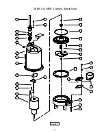
F-4.3) Wiring Connections:
Check power cords (16) and control cord (56, if used), for
cracks or damage and replace if required (see Figure 12).
Make internal wiring connections which are independent of
the terminal block as shown, using connectors (48) and wire
assemblies (49) as required.
Do not
use wire nuts. Slip motor
leads and ground wire into fiberglass sleeve. Lower motor
housing (6) down onto seal plate (5) while aligning holes and
stringing motor leads through the cord entry bore(s). (Slipping
cords inside a 1 ft. length of .5” conduit makes this easier).
Place socket head cap screws (47) through seal plate (5) into
motor housing (6) and torque to 60 in-lbs.
FIGURE 13
FIGURE 12
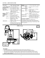
Summary of Contents for 2SEV-DS Series
Page 16: ...16 FIGURE 15 CONTIUED...
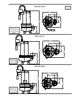
Page 18: ...18 FIGURE 16 2SEV L 3SEV L Series Single Seal...
Page 19: ...19 FIGURE 17 2SEV L 3SEV L Series Single Seal...
Page 20: ...20 FIGURE 18 2SEV DS 3SEV DS Series Double Seal...
Page 21: ...21 FIGURE 19 2SEV DS 3SEV DS Series Double Seal...
Page 25: ...25 Notes...
Page 26: ...26 Notes...


