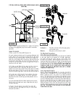
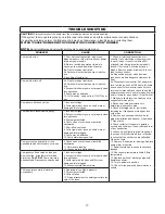
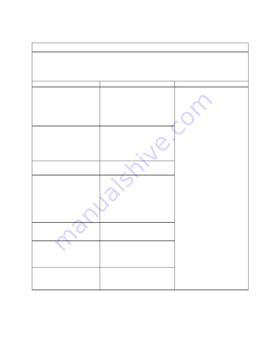
Barnes 2SEV-DS Series Installation And Operation Manual Download Page 17

17

TROUBLE SHOOTING

CAUTION !

 Always disconnect the pump from the electrical power source before handling.

If the system fails to operate properly, carefully read instructions and perform maintenance recommendations.

If operating problems persist, the following chart may be of assistance in identifying and correcting them:

MATCH “CAUSE” NUMBER WITH CORRELATING “CORRECTION” NUMBER

.

NOTE:

 Not all problems and corrections will apply to each pump model.

PROBLEM

CAUSE

CORRECTION

Pump will not run

1.

 Poor electrical connection, blown fuse, 

tripped breaker or other interruption of power, 

improper power supply.

2.

 Motor or switch inoperative (to isolate 

cause, go to manual operation of pump).

2a.

 Flaot movement restricted.

2b. Switch will not activate pump or is defec-

tive.

3.

 Insufficient liquid level.

1. Check all electrical connections for 

security. Have electrician measure current 

in motor leads, if current is within ±20% 

of locked rotor Amps, impeller is probably 

locked. If current is 0, overload may be 

tripped. Remove power, allow pump to cool, 

then recheck current.

2a. Reposition pump or clean basin as 

required to provide adequate clearance for 

float.

2b. Disconnect level control. Set ohmmeter 

for a low range, such as 100 ohms full scale 

and connect to level control leads. Actuate 

level control manually and check to see that 

ohmmeter shows zero ohms for closed switch 

and full scale for open switch. (Float Switch).

3. Make sure liquid level is at least equal to 

suggested turn-on point.

4. Recheck all sizing calculations to 

determine proper pump size.

5. Check discharge line for restrictions, 

including ice if line passes through or into 

cold areas.

6. Remove and examine check valve for 

proper installation and freedom of operation.

7. Open valve.

8. Check cutter for freedom of operation, 

security and condition. Clean cutter and inlet 

of any obstruction.

9. Loosen union slightly to allow trapped air 

to escape.Verify that turn-off level of switch 

is set so that the suction is always flooded. 

Clean vent hole.

10. Remove & examine for damage. Replace 

pump stator if required.

11. Repair fixtures as required to eliminate 

leakage.

12. Check pump temperature limits & fluid 

temperature.

13. Replace portion of discharge pipe with 

flexible connector.

14. Turn to automatic position.

15. Check for leaks around basin inlet and 

outlets.

Pump will not turn off

2a. Float movement restricted.

2b. Switch will not activate pump or is defec-

tive.

4. Excessive inflow or pump not properly sized 

for application.

9. Pump may be airlocked.

14. H-O-A switch  on panel is in “HAND” posi-

tion

Pump hums but does not run

1. Incorrect voltage

8. Cutter jammed or loose on shaft, worn or 

damaged, inlet plugged.

Pump delivers insufficient capacity

1. Incorrect voltage.

4. Excessive inflow or pump not properly sized 

for application.

5. Discharge restricted.

6. Check valve stuck closed or installed 

backwards.

7. Shut-off valve closed.

8. Cutter jammed or loose on shaft, worn or 

damaged, inlet plugged.

9. Pump may be airlocked.

10. Pump stator damaged/torn.

Pump cycles too frequently or runs 

periodically when fixtures are not in use

6. Check valve stuck closed or installed 

backwards.

11. Fixtures are leaking.

15. Ground water entering basin.

Pump shuts off and turns on indepen

-

dent of switch, (trips thermal overload 

protector). 

CAUTION!

  Pump may start 

unexpectedly. Disconnect power supply.

1. Incorrect voltage.

4. Excessive inflow or pump not properly sized 

for application.

8. Cutter jammed, loose on shaft, worn or 

damaged, inlet plugged.

12. Excessive water temperature.

Pump operates noisily or vibrates 

excessively

4. Operating at too high a pressure.

5. Discharge restricted.

8. Cutter broken.

13. Piping attachments to buiding structure too 

rigid or too loose.

Summary of Contents for 2SEV-DS Series

Page 1: ...ct improvement program product changes may occur As such Crane Pumps Systems reserves the right to change product without prior written notification 420 Third Street 83 West Drive Bramton Piqua Ohio 4...

Page 2: ...ig 17 19 DOUBLE SEAL CROSS SECTION Fig 18 20 DOUBLE SEAL EXPLODED VIEW Fig 19 21 PARTS LIST 22 24 RETURNED GOODS POLICY 28 WARRANTY 27 WARRANTY REGISTRATION SPECIAL TOOLS AND EQUIPMENT INSULATION TEST...

Page 3: ...rt fingers in pump with power connected Always wear eye protection when working on pumps Make sure lifting handles are securely fastened each time before lifting DO NOT operate pump without safety dev...

Page 4: ...n Insulation Class B Class F on selected models SINGLE PHASE Permanent Split Capacitor PSC Includes overload protection in motor THREE PHASE 200 240 480 is Tri voltage motor 600V Requires overload pro...

Page 5: ...2SEV DS Series 3SEV L Series 3SEV DS Series Plugs for 120 Volt and 5Hp 240 Volt Single Phase Models Plugs for 120 Volt and 5Hp 240 Volt Single Phase Models Plugs for 120 Volt and 5Hp 240 Volt Single P...

Page 6: ...or basin that is free of hard debris like gravel stones sand or earth The sump lift station or basin shall be vented in accordance with local plumbing codes This pump is designed to pump sewage efflu...

Page 7: ...operations Automatic Plug float cord into outlet then plug pump cord into float cord Manual Plug pump cord directly int outlet C 4 Electrical Connections C 4 1 Power and Control Cords The cord assemb...

Page 8: ...04986 1 0 600 3 60 3450 L B 2 9 8 7 14 4 SOW 0 570 14 5 21 20 34 57 2SEV514DS 104923 0 5 120 1 60 1750 F B 12 0 21 3 14 3 SJTOW 0 375 9 5 1 51 16 10 2SEV524DS 104924 0 5 240 1 60 1750 J B 6 3 14 9 14...

Page 9: ...05008 1 0 600 3 60 3450 L B 2 9 8 7 14 4 SOW 0 570 14 5 21 20 34 57 3SEV514DS 104949 0 5 120 1 60 1750 F B 12 0 21 3 14 3 SJTOW 0 375 9 5 1 51 16 10 3SEV524DS 104950 0 5 240 1 60 1750 J B 6 3 14 9 14...

Page 10: ...e for the first time the motor rotation must be checked Improper motor rotation can result in poor pump performance and can damage the motor and or pump To check the rotation suspend the pump freely m...

Page 11: ...are observed slowly bleed the pressure and remove the gauge assembly Replace oil as described in section F 1 4 If the pressure does not hold then the leak must be located and repaired Pumps that have...

Page 12: ...Apply thread locking compound 57 to shaft threads then install jam nut 66 and torque to 40 ft lbs It is important that the spring of the lower shaft seal 28 seats in the hub of the impeller 33 Rotate...

Page 13: ...28b are together see Figure 8 It is extremely important to keep seal faces clean during assembly Dirt particles lodged between these faces will cause the seal to leak Place spring 28c over shaft and...

Page 14: ...eck rotor for wear If rotor or the stator windings are defective the complete motor must be replaced Important All parts must be clean before reassembly F 4 2 Reassembly Moisture Sensors DS Models If...

Page 15: ...the following information 1 Pump serial number and date code Paragraph G 4 2 Pump model number Paragraph G 3 3 Pump part number Paragraph G 2 4 Part description 5 Item part number 6 Quantity required...

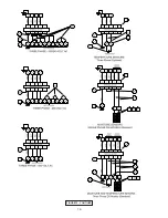
Page 16: ...16 FIGURE 15 CONTIUED...

Page 17: ...cutter for freedom of operation security and condition Clean cutter and inlet of any obstruction 9 Loosen union slightly to allow trapped air to escape Verify that turn off level of switch is set so...

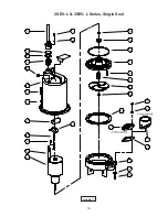
Page 18: ...18 FIGURE 16 2SEV L 3SEV L Series Single Seal...

Page 19: ...19 FIGURE 17 2SEV L 3SEV L Series Single Seal...

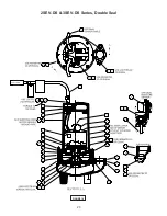
Page 20: ...20 FIGURE 18 2SEV DS 3SEV DS Series Double Seal...

Page 21: ...21 FIGURE 19 2SEV DS 3SEV DS Series Double Seal...

Page 22: ...44DS 2SEV1094DS 2SEV1044DS 071354BD 3SEV1094DS 3SEV1044DS 092855BS 2SEV754L 3SEV754L 2SEV1054L 3SEV1054L 092855BD 2SEV754DS 3SEV754DS 2SEV1054DS 3SEV1054DS 068926BS 2SEV512L 3SEV512L 068926BD 2SEV512D...

Page 23: ...27008 62 Retaining Ring All double seal 33 1 Impeller Cast Iron 3450RPM 105144TH 4 25 Dia STD for a 1 0 HP 105144TJ 4 13 Dia 105144TK 4 00 Dia 105144TL 3 88 Dia 105144TM 3 75 Dia 105144TN 3 63 Dia 105...

Page 24: ...25 02117 Sleeve Fiberglass 66 1 030068 Jam Nut 1 2 20 SS 69 1 111909 Jumper Wire TABLE 2 POWER SENSOR CORD SETS CABLE LENGTH ITEM 16 120 VOLT 1 PHASE plug included ITEM 16 240 VOLT 1 PHASE 0 5HP plug...

Page 25: ...25 Notes...

Page 26: ...26 Notes...

Page 27: ...A RETURNED GOODS AUTHORIZATION CONTACT YOUR LOCAL CRANE PUMPS SYSTEMS INC DISTRIBUTOR Products Returned Must Be Cleaned Sanitized Or Decontaminated As Necessary Prior To Shipment To Insure That Employ...

Reviews: