background image


11 


7


Insert a new induction sensor and connect the sensor to the motor 
controller PCB, see step 6.


8


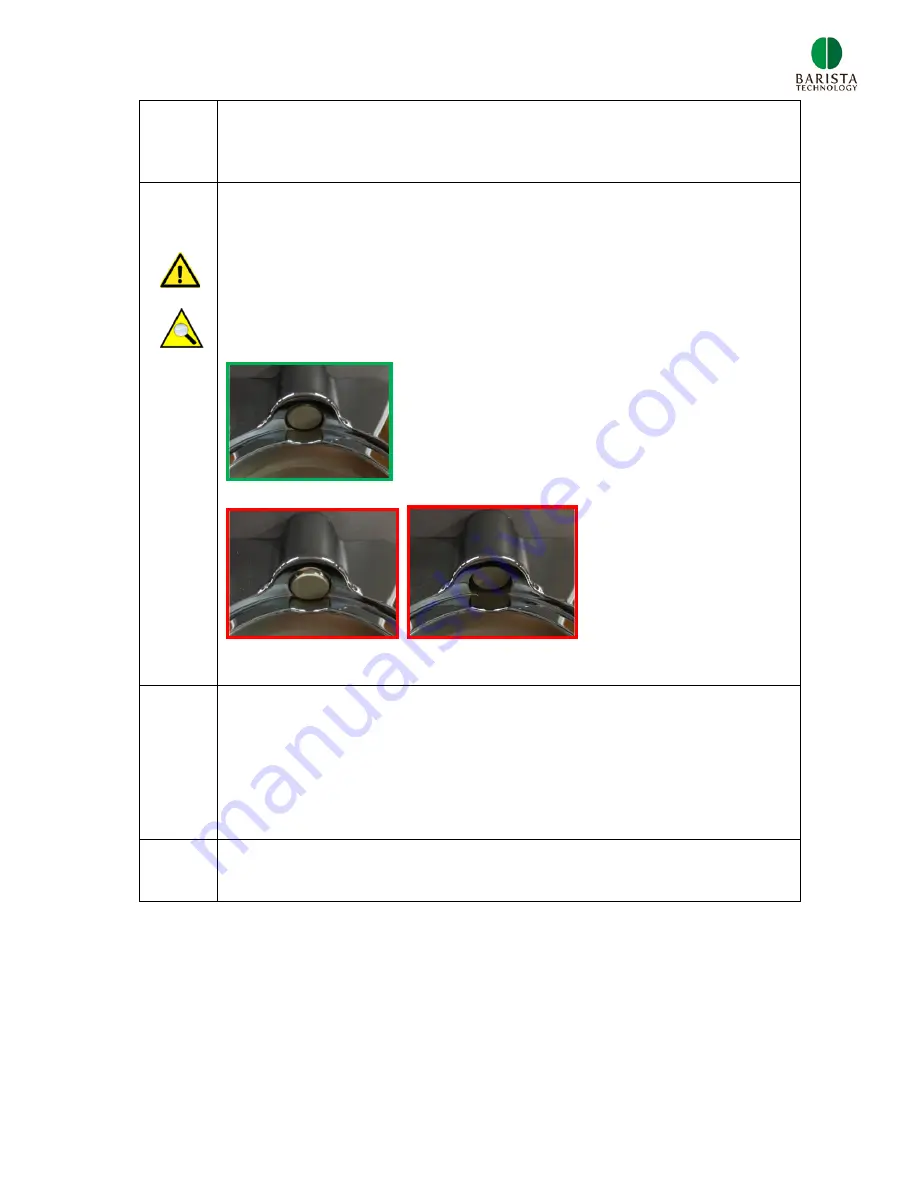
Fasten the set screw M5, see step 5.  
 

Critical: The sensor does not function when too much torque 
is applied

.  

 
Check the position of the sensor after assembly 


Correct


NOT correct                      NOT correct 


9


Mount the main housing – back cover, see step 3 
 
Mount the main housing – middle cover, see step 2.  
 
Mount the main housing – top cover, step 1.  


10


Check functioning of the new induction sensor. 


Summary of Contents for PUQpress

Page 1: ...Maintenance repair manual Puqpress Precision coffee tamper VERSION 2 0 4 DATE 14 12 2016 ...

Page 2: ...n tamper base daily cleaning 12 3 4 Remove tamper base and clean cavity weekly cleaning 13 3 5 Adjust lower clamp 15 3 6 Adjust tamping force 17 4 Changing tamper base 18 4 1 Upper clamp types 18 4 2 Determine upper clamp type 18 4 3 Espresso machine brand and tamper diameter 19 5 Exploded view Total assembly 19 6 Order spare parts 20 6 1 Order procedure 20 6 2 Recommended spare parts 20 6 3 Part ...

Page 3: ...owledge of electrical and mechanical components 1 1 Warranty As agreed by the Exclusive distribution agreement section 6 7 the warranty period of the product is 12 month and or 100 000 tamping cycles whichever first occurs Repairs after this period are not covered by the supplier The most common failure mode is the drive unit After many cycles the drive unit wears and can break Replacement of driv...

Page 4: ...ng is not level Lower clamp not correctly set and portafilter can rotate Adjust lower clamp 3 5 Tamping force is too low Force setting too low Adjust tamping force on display 3 6 Fault in drive unit Clean drive unit 3 1 Fault in drive unit Replace drive unit 3 1 Tamper diameter not correct Change to other tamper base diameter Change tamper base 4 1 Change from 58mm base to 53mm or 53mm to 58mm Cha...

Page 5: ...1 Switch the device ON and activate the CLEAN mode Tamper base goes down Switch OFF and remove power cable 2 Remove main housing top cover 3 Remove the hexagon bolt M5x100 spring washer M5 using the Allen key 4mm Remove the tamper base NOTE Tamper base has left hand screw thread ...

Page 6: ...cover which is mounted to the main body with 3 cross head cap screws M4x10 5 Unscrew 2 screws as is shown in the figure below 6 Open the main housing back cover NOTE the push buttons red are fragile so be careful when opening back cover ...

Page 7: ...7 7 Disconnect the earthing cable from the DC worm gear motor 8 Unscrew 2 hexagon head cap screws M5x25 9 Disconnect the connectors as are shown in the figures below ...

Page 8: ...ws M5x25 Apply Permabond A1042 on screw threads 12 Connect both connectors see step 9 Fasten the earthing cable to the DC motor see step 8 Mount the main housing back cover see step 5 Mount the main housing middle cover see step 4 Mount the tamper base see step 3 Mount the main housing top cover step 2 13 Check functioning of new drive unit ...

Page 9: ...ction sensor Step Description 1 Remove main housing top cover 2 Remove the main housing middle cover which is mounted to the main body with 3 cross head cap screws M4x10 3 Unscrew 2 screws as is shown in the figure below ...

Page 10: ...are fragile so be careful when opening back cover 5 The sensor is fixed with a set screw M5 Unscrew the set screw using Allen key 2 5mm via the hole as shown below The drive units doesn t need to be removed 6 Remove the induction sensor and disconnect the connector ...

Page 11: ...5 Critical The sensor does not function when too much torque is applied Check the position of the sensor after assembly Correct NOT correct NOT correct 9 Mount the main housing back cover see step 3 Mount the main housing middle cover see step 2 Mount the main housing top cover step 1 10 Check functioning of the new induction sensor ...

Page 12: ... support videos www puqpress com support Step Description 1 Turn unit ON and push the CLEAN button Tamper base goes down completely 2 Clean the tamper base with a dry towel or a brush 3 Push the clean button again tamper base goes up Cleaning finished ...

Page 13: ... support videos www puqpress com support Step Description 1 Switch the device ON and activate the CLEAN mode Tamper base goes down Switch OFF and remove power cable 2 Remove main housing top cover 3 Remove the hexagon bolt M5x100 spring washer M5 using the Allen key 4mm ...

Page 14: ...se NOTE Tamper base has left hand screw thread 5 Clean cavity with a brush 6 After cleaning Mount tamper base step 4 Fasten tamper base with M5x100 hex cap screw and spring lock washer step 3 Mount main housing top cover step 2 ...

Page 15: ...r cable and switch the Puqpress ON Tamper heads moves to upper position 2 Remove power cable 3 Put the unit with back side in the white packing box Unscrew both bolts as is shown below You can find the right tool in the box 4 Insert the portafilter and push the lower clamp upwards Fasten both bolts slightly ...

Page 16: ...r clamp Fasten both bolts firmly 6 Insert the portafilter again and check fitting Lower clamp might be moved during fastening of bolts 7 Incorrect setting The portafilter should be clamped properly to ensure level tamping Movement of portafilter should be minimal Pictures below show incorrect setting ...

Page 17: ...17 3 6 Adjust tamping force Check our support videos www puqpress com support Step Description 1 Change tamping force with push buttons ...

Page 18: ...1 by the red arrow Why are we using two types of upper clamps If the U groove is too big compared to the outer diameter of the filter basket level tamping cannot be guaranteed 4 2 Determine upper clamp type The type of upper clamp is defined by the external diameter of the filter basket In order to determine the correct upper clamp type measure the outer diameter of the filter basket using a calli...

Page 19: ...rd and need another upper clamp size Therefore check the outer and inner diameter of the filter basket in order to pick the correct setting 4 3 Espresso machine brand and tamper diameter Espresso machine brand Tamper base diameter Astoria 58 Bezzera 58 Brasilia 58 Caramali 58 Cimbali 57 Conti 58 ECM 58 Elektra 58 Expobar 58 Faema 58 Gaggia 58 La Marzocco 58 La Pavoni 56 Nuova Simonelli 58 Pasquini...

Page 20: ...ean cycles counter 1 Turn unit ON and put unit in CLEAN modus tamper disk goes down 2 Hold button button for 3 seconds 3 Display blinks and shows a number multiply this number by 5 max clean cycle counter is 99 5 4 Cycle counter disappears after 5 seconds 5 3 20 cycle run in mode 1 Turn unit OFF Hold CLEAN button and button and turn unit ON CF appears on display 2 Push button 3 Unit start to tamp ...

Page 21: ... setting in KG 4 Push CLEAN button twice to go back to standby mode 5 5 Reset tamping cycle clean cycle counter 1 Turn unit OFF Hold CLEAN button and button and turn unit ON CF appears on display 2 Push CLEAN button twice Fr appears on display 3 Push Hold button for 1s and then button for 1s to restore clean and tamping cycle counter 4 rr appear on display when counter has been reset 5 Push CLEAN ...

Page 22: ...3 111 1 C_upper_clamp Upper clamp chromium plated 1 21 1 210 0060 1 111 1 B_display_sticker Display sticker 1 22 1 110 0014 1 111 1 A_on_off_switch On off switch 1 23 1 110 0031 2 111 1 A_plastic_screw_4x12 PT screw for plastic 2 24 1 210 0001 3 111 1 D_main_body Main body 1 25 1 210 0020 2 111 1 A_main_housing_back_cover Main housing back cover 1 26 1 210 0021 1 111 1 D_main_housing_middle_cover ...

Page 23: ... 1 111 1 A_countersunk_screw_M5x12 Flat head countersunk socket M5x12 1 6 1 110 0026 111 1 A_hex_cap_screw_M5x12 Hex socket head cap screw M5x12 2 7 1 210 0057 1 111 1 B_spur_gear Spur gear 1 8 1 210 0025 2 111 1 A_motor_frame Motor frame 1 9 1 110 0075 1 111 1 A_hex_cap_screw_M5x100 Hexagon head cap screw M5x100 1 REVISIONS REV DESCRIPTION DATE APPROVED A 10 1 2016 L PLUIMERS Assy drive unit WEIG...

Page 24: ...place complete Drive Unit 1 310 0001 1 1 110 0014 1 On off switch 1 210 0005 3 Upper clamp size 71 1 210 0010 1 Upper clamp size 66 1 210 0015 2 Lower clamp 1 210 0020 1 Main housing back cover 1 210 0021 1 Main housing middle cover 1 210 0022 1 Main housing top cover 1 210 0025 2 Motor frame 1 210 0030 1 Ground coffee basket 1 210 0035 1 Anti slip foot per piece 1 210 0043 1 Tamper disk 58 3mm VS...

Page 25: ... 0035 1 Anti slip foot per piece 1 210 0040 1 Counterweight 1 210 0044 1 Electrical insulation foil 1 210 0049 1 Tamper disk 59mm 1 210 0043 1 Tamper disk 58 3mm VST 1 210 0050 2 Tamper disk 58mm 1 210 0051 1 Tamper disk 57mm 1 210 0052 1 Tamper disk 56mm 1 210 0053 1 Tamper disk 55mm 1 210 0054 1 Tamper disk 54mm 1 210 0055 1 Tamper disk 53mm 1 210 0056 2 Rack shaft 1 210 0057 1 Spur gear 1 210 0...

Reviews: