background image

Manual 2100-498B
Page

13 of 17

0

50

100

150

200

250

300

350

400

450

500

550

600

650

closed

A

B

C

D

Open

Damper Position

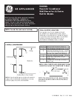
W30-36G EIFM Airflow Versus Position - Low Speed

Free Blow
.15" ESP
.30" ESP

0

50

100

150

200

250

300

350

400

450

500

550

600

650

700

750

closed

A

B

C

D

Open

Damper Position

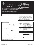
W30-36G EIFM Airflow Versus Position - Medium 

Speed

Free Blow
.15" ESP
.30" ESP

0

50

100

150

200

250

300

350

400

450

500

550

600

650

700

750

800

closed

A

B

C

D

Open

Damper Position

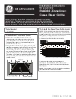
W30-36G EIFM Airflow Versus Position - High 

Speed

Free Blow
.15" ESP
.30" ESP

Fresh Air 

CFM

Fresh Air 

CFM

Fresh Air 

CFM

Summary of Contents for WGEIFM-3C

Page 1: ...th Bard 3 5 Ton Step Capacity and 2 5 Ton Single Stage Wall Mount Air Conditioners with Gas Heat INSTALLATION INSTRUCTIONS Copyright 2007 Manual 2100 498B Supersedes 2100 498A File Volume III Tab 19 D...

Page 2: ...Wire Harness 6 Figure 4 WGSEIFM 5 Wiring Diagram 7 Figure 5 Economizer Logic Module 9 Figure 6 Economizer Op Single Compressor 15 Figure 7 Call for Blower Operation 16 Figure 8 Call for Cooling Opera...

Page 3: ...s agent Concealed damage not discovered until after loading must be reported to the carrier within 15 days of its receipt DESCRIPTION The WGEIFM 3C economizer is designed to be used with Bard W24G to...

Page 4: ...e Figure 1 3 Remove and discard exhaust cover plate see Figure 1 4 In rear of opening towards duct connection install exhaust opening adaptor plate included WARNING Open and lock unit disconnect switc...

Page 5: ...of the condenser grille See Figure 2 IMPORTANT Position front lip of ventilator on top of front grille and condenser partition See Figure 2 inset This is important to ensure proper drainage of any wa...

Page 6: ...100 498B Page 6 of 17 FIGURE 3 INSTALL LOOSE PIECE WIRE HARNESS PLUG SECURE INTO FILTER TRAY PLUG TO ROUTE WIRES THROUGH WIRE MOUNT AND INTO HOLE AT REAR OF UNIT INTO LOW VOLTAGE TERMINAL BLOCK AREA M...

Page 7: ...ERMINAL STRIP EIFM CONTROL PANEL UNIT BLOWER SECTION 1 1 2 2 3 3 6 6 5 5 4 4 8 8 7 7 PL1 PL2 BLACK SERVICING S C G Y Y1 R Y2 F E W1 W2 1 2 3 1 3 4 7 A B 6 9 TH P P1 T1 T 4 3 1 2 5 Sr So BK 6 ENTHALPY...

Page 8: ...iently low If enthalpy is too high for economizing low enthalpy can be simulated by temporarily removing and jumping leads on terminals 2 and 3 of enthalpy control together This will also cause the ec...

Page 9: ...Manual 2100 498B Page 9 of 17 FIGURE 5 ECONOMIZER LOGIC MODULE...

Page 10: ...5 17 5 20 22 5 25 27 5 30 Vent Position Ventilation Airflow CFM Stage 2 Operation Blower Only Stage 1 Operation WG4S Ventilation Airflow 0 100 200 300 400 500 600 700 800 900 0 2 5 5 7 5 10 12 5 15 17...

Page 11: ...Page 11 of 17 WG5S Ventilation Airflow 0 100 200 300 400 500 600 700 800 900 1000 0 2 5 5 7 5 10 12 5 15 17 5 20 22 5 25 27 5 30 Vent Position Ventilation Airflow CFM Stage 2 Operation Stage 1 Operat...

Page 12: ...0 ESP 0 50 100 150 200 250 300 350 400 450 500 550 600 650 700 closed A B C D Open Damper Position W24G EIFM Airflow Versus Position Medium Speed Free Blow 15 ESP 30 ESP 0 50 100 150 200 250 300 350 4...

Page 13: ...SP 0 50 100 150 200 250 300 350 400 450 500 550 600 650 700 750 closed A B C D Open Damper Position W30 36G EIFM Airflow VersusPosition Medium Speed Free Blow 15 ESP 30 ESP 0 50 100 150 200 250 300 35...

Page 14: ...100 150 200 250 300 350 400 450 500 550 600 650 700 750 800 closed A B C D Open Damper Position W42 60G EIFM Airflow VersusPosition Medium Speed Free Blow 0 15 ESP 0 30 ESP 0 50 100 150 200 250 300 35...

Page 15: ...Manual 2100 498B Page 15 of 17 FIGURE 6 ECONOMIZER OPERATION FOR SINGLE COMPRESSOR UNIT...

Page 16: ...economizer dampers to economizer mode and the indoor blower starts Mixed Air Sensor senses a mixture of return air and outdoor air and modulates the dampers accordingly Compressor operation is inhibit...

Page 17: ...Manual 2100 498B Page 17 of 17 CONDITION B WARM OUTDOORS First stage cooling cycles the compressor and dampers remain in mechanical cooling mode FIGURE 8 CALL FOR COOLING OPERATION...

Reviews: