


Manual 2100-365
Page 22
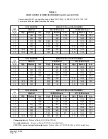
U. S. INSTALLATIONS ONLY
Ratings of gas utilization equipment are based on sea
level operation and need not be changed for operation
at elevations up to 2,000 feet. For operation at
elevations above 2,000 feet, and in the absence of
specific recommendations from the local authority
having jurisdiction, equipment ratings shall be
reduced at the rate of 4 percent per each 1,000 feet
above sea level before selecting appropriately sized
equipment. (Ref. ANSI Z223.1 - latest edition). See
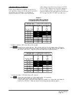
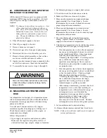
Table 7 for high altitude derate information, and for
fuel gas BTU ratings from 800-1100 BTU per cubic
foot.
At higher altitudes, the density of the air is reduced.
Therefore, for proper combustion, the quantity of gas
burned in the furnace must also be reduced. This is
called derating. Furnaces must be derated when
installed at altitudes greater than 2,000 feet above sea
level.
At elevations above 2,000 feet the furnace must be
derated. It is the installer’s responsibility to see that
the furnace input rate is adjusted properly. Derating
must be achieved by reducing the size of the main
burner orifices. Derating the furnace by adjusting the
manifold pressure lower than the range specified in
the Section 16, "Manifold Pressure Adjustment" is
considered to be an improper procedure.
TABLE 7
HIGH ALTITUDE DERATE CHARTS
U.S. INSTALLATIONS ONLY
-
-
S
A
G
L
A
R
U
T
A
N
R
O
F
T
R
A
H
C
E
Z
I
S
E
C
I
F
I
R
O
0
0
5
,
2
2
N
O
I
T
P
O
D
E
L
L
A
T
S
N
I
D
L
E
I
F
R
E
N
R
U
B
R
E
P
U
T
B
t
a
e
H
s
a
G
*
e
u
l
a
V
.
t
F
.
u
C
/
U
T
B
o
t
p
U
0
0
0
2
t
e
e
F
1
0
0
2
o
t
0
0
0
3
t
e
e
F
1
0
0
3
o
t
0
0
0
4
t
e
e
F
1
0
0
4
o
t
0
0
0
5
t
e
e
F
1
0
0
5
o
t
0
0
0
6
t
e
e
F
1
0
0
6
o
t
0
0
0
7
t
e
e
F
1
0
0
7
o
t
0
0
0
8
t
e
e
F
1
0
0
8
o
t
0
0
0
9
t
e
e
F
1
0
0
9
o
t
0
0
0
0
1
t
e
e
F
9
4
8
-
0
0
8
0
5
.
2
5
4
.
2
5
4
.
2
0
4
.
2
5
3
.
2
0
3
.
2
5
2
.
2
0
2
.
2
5
1
.
2
9
9
8
-
0
8
8
0
5
.
2
0
4
.
2
5
3
.
2
0
3
.
2
0
3
.
2
5
2
.
2
0
2
.
2
5
1
.
2
0
1
.
2
9
4
9
-
0
0
9
0
4
.
2
0
3
.
2
0
3
.
2
5
2
.
2
0
2
.
2
0
2
.
2
5
1
.
2
0
1
.
2
5
0
.
2
9
9
9
-
0
5
9
5
3
.
2
5
2
.
2
5
2
.
2
0
2
.
2
0
2
.
2
5
1
.
2
0
1
.
2
5
0
.
2
0
0
.
2
9
4
0
1
-
0
0
0
1
0
3
.
2
0
2
.
2
0
2
.
2
5
1
.
2
0
1
.
2
0
1
.
2
5
0
.
2
0
0
.
2
5
9
.
1
0
0
1
1
-
0
5
0
1
5
2
.
2
5
1
.
2
5
1
.
2
0
1
.
2
0
1
.
2
5
0
.
2
0
0
.
2
5
9
.
1
0
9
.
1
* At standard conditions: 30.00 inches Mercury, 60F, saturated.
NOTE:
2.30
Orifices are shipped with the unit for field installed optional 10% input derate.
2.40
is the factory installed orifice size for full rated input.
All other orifice sizes not shown with black background are available in U.S. Natural Gas High Altitude Kit,
Bard Part No. GCK-US-N1. Orifice sizes shown with black background available separately.
-
-
S
A
G
L
A
R
U
T
A
N
R
O
F
T
R
A
H
C
E
Z
I
S
E
C
I
F
I
R
O
0
0
0
,
5
2
D
R
A
D
N
A
T
S
Y
R
O
T
C
A
F
R
E
N
R
U
B
R
E
P
U
T
B
t
a
e
H
s
a
G
*
e
u
l
a
V
.
t
F
.
u
C
/
U
T
B
o
t
p
U
0
0
0
2
t
e
e
F
1
0
0
2
o
t
0
0
0
3
t
e
e
F
1
0
0
3
o
t
0
0
0
4
t
e
e
F
1
0
0
4
o
t
0
0
0
5
t
e
e
F
1
0
0
5
o
t
0
0
0
6
t
e
e
F
1
0
0
6
o
t
0
0
0
7
t
e
e
F
1
0
0
7
o
t
0
0
0
8
t
e
e
F
1
0
0
8
o
t
0
0
0
9
t
e
e
F
1
0
0
9
o
t
0
0
0
0
1
t
e
e
F
9
4
8
-
0
0
8
0
7
.
2
0
6
.
2
0
5
.
2
0
5
.
2
5
4
.
2
0
4
.
2
5
3
.
2
0
3
.
2
0
3
.
2
9
9
8
-
0
8
8
0
6
.
2
0
5
.
2
5
4
.
2
0
4
.
2
0
4
.
2
0
3
.
2
0
3
.
2
5
2
.
2
0
2
.
2
9
4
9
-
0
0
9
0
5
.
2
0
4
.
2
5
3
.
2
5
3
.
2
0
3
.
2
5
2
.
2
0
2
.
2
5
1
.
2
0
1
.
2
9
9
9
-
0
5
9
5
4
.
2
5
3
.
2
0
3
.
2
0
3
.
2
5
2
.
2
0
2
.
2
5
1
.
2
0
1
.
2
5
0
.
2
9
4
0
1
-
0
0
0
1
0
4
.
2
0
3
.
2
0
3
.
2
0
2
.
2
0
2
.
2
5
1
.
2
0
1
.
2
5
0
.
2
0
0
.
2
0
0
1
1
-
0
5
0
1
0
3
.
2
5
2
.
2
0
2
.
2
5
1
.
2
5
1
.
2
0
1
.
2
5
0
.
2
0
0
.
2
5
9
.
1
* At standard conditions: 30.00 inches Mercury, 60F, saturated.
NOTE:
2.40
Standard factory installed orifice size.
2.30
is shipped with the unit for field installed optional 10% derate.
All orifice sizes not shown with black background are available in U.S. Natural Gas High Altitude Kit, Bard
Part No. GCK-US-N1. Orifice sizes shown with black background available separately.
Summary of Contents for WG421
Page 8: ...Manual 2100 365 Page 5 MIS 1352 FIGURE 1 UNIT DIMENSIONS...
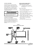
Page 12: ...Manual 2100 365 Page 9 FIGURE 4 MOUNTING INSTRUCTIONS MIS 1472...
Page 15: ...Manual 2100 365 Page 12 FIGURE 8 COMMON WALL MOUNTING INSTALLATIONS MIS 1474...
Page 20: ...Manual 2100 365 Page 17 FIGURE 11 LOW VOLTAGE WIRING MIS 1162...
Page 21: ...Manual 2100 365 Page 18 FIGURE 12 GAS PIPE CONNECTION MIS 1478...
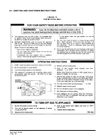
Page 29: ...Manual 2100 365 Page 26 26 LIGHTING AND SHUTDOWN INSTRUCTIONS FIGURE 14 INSTRUCTION LABEL...
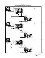
Page 34: ...Manual 2100 365 Page 31 FIGURE 18 460 VOLT BLOWER MOTOR WIRING OPTIONS MIS 1487 A B C...
Page 41: ...Manual 2100 365 Page 38...
Page 42: ...Manual 2100 365 Page 39...
Page 43: ...Manual 2100 365 Page 40...
Page 44: ...Manual 2100 365 Page 41...
Page 45: ...Manual 2100 365 Page 42...
Page 46: ...Manual 2100 365 Page 43...
Page 47: ...Manual 2100 365 Page 44...
Page 48: ...Manual 2100 365 Page 45...
Page 49: ...Manual 2100 365 Page 46...
Page 50: ...Manual 2100 365 Page 47...
Page 51: ...Manual 2100 365 Page 48...
Page 52: ...Manual 2100 365 Page 49...


