


Manual 2100-416L
Page
21 of 29
TAP
RANGE
240V
253 - 216
208V
220 - 18
Thermostat
Predominant Features
8403-060
(1120-445)
3 stage Cool; 3 stage Heat
Programmable/Non-Programmable
Electronic
HP or Conventional
Auto or Manual changeover
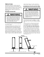
The unit rating plate lists a “Maximum Time Delay
Relay Fuse” or circuit breaker that is to be used with
the equipment. The correct size must be used for
proper circuit protection and also to assure that there
will be no nuisance tripping due to the momentary high
starting current of the compressor motor.
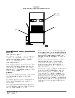
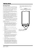
The disconnect access door on this unit may be locked
to prevent unauthorized access to the disconnect.
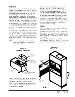
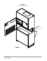
The field wiring connections are located behind the
top panel in the circuit breaker panel. The return air
panel must be removed first. This panel is equipped
with a door switch which shuts the unit down when it is
removed. The filter rack must be removed next.
Wiring – Low Voltage
All 230/208V 1 phase and 3 phase equipment have
dual primary voltage transformers. All equipment leaves
the factory wired on 240V tap. For 208V operation,
reconnect from 240V to 208V tap. The acceptable
operating voltage range for the 240 and 208V taps are
as noted in Table 4.
NOTE:
The voltage should be measured at the field
power connection point in the unit and while
the unit is operating at full load (maximum
amperage operating condition).
TABLE 4
Operating Voltage Range
TABLE 5
Wall Thermostat
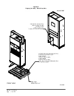
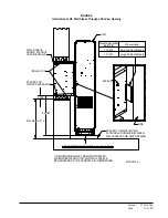
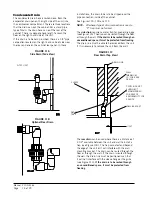
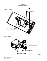
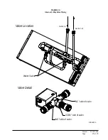
Fluid Connections
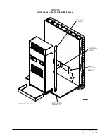
See Figure 1 on page 6 for location of fluid connection.
Connection size is 1" FPT.
If the free blow plenum box is to be used, there are
knockouts in the top of the box that can be removed to
allow passage of the fluid piping.
All plumbing to and from the unit is to be installed
in accordance with local plumbing codes. The use of
plastic pipe where permissible is recommended to
prevent electrolytic corrosion of the fluid pipes.
It is strongly recommended that the fluid piping to
the unit be insulated to prevent water droplets from
condensing on the pipe surface.
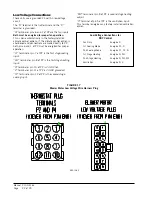
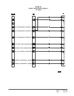
The standard Climate Control
Option X
is a remote
thermostat connection terminal block. See Figure 18
on page 23 for wiring diagram. Compatible thermostat
is listed in Table 5.
CAUTION
Do not plug in or unplug blower motor
connectors while the power is on.
Failure to do so may result in motor failure.
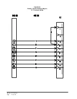
The Climate Control
Option D
is an electronic,
programmable thermostat. The subbase of the
thermostat is factory wired to the front panel of the
unit. Compatible for use with energy recovery ventilator
or economizer.
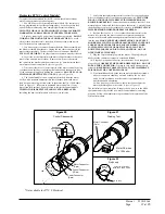
General
This unit is equipped with a variable speed ECM motor.
The motor is designed to maintain rated airflow up to
the maximum static allowed.
It is important that the
blower motor plugs are not plugged in or unplugged
while the power is on. Failure to remove power prior
to unplugging or plugging in the motor could result in
motor failure.
Summary of Contents for QC Series
Page 6: ...Manual 2100 416L Page 6 of 29 FIGURE 1 Unit Dimensions...
Page 16: ...Manual 2100 416L Page 16 of 29 FIGURE 12 Fresh Air Damper Removal MOUNTING SCREW...
Page 23: ...Manual 2100 416L Page 23 of 29 FIGURE 18 Remote Thermostat Wiring Diagram X Option...
Page 24: ...Manual 2100 416L Page 24 of 29 FIGURE 19 Remote Thermostat Wiring Diagram D Thermostat Option...


