


Manual 2100-416L
Page
2 of 29
CONTENTS
Getting Other Information and Publications .... 3
QC
Seris Water Source General Information ...... 4
QC
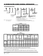
Model Nomenclature ....................................... 4
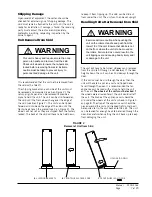
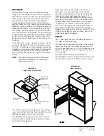
Shipping Damage ................................................. 7
Unit Removal From Skid ....................................... 7
Handling Unit After Removal From Skid ................. 7
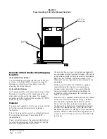
Removal of Wall Bracket from Shipping Location ..... 8
General ............................................................... 8
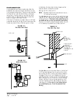
Minimum Installation Height ................................. 9
Duct Work ......................................................... 13
Filters ............................................................... 13
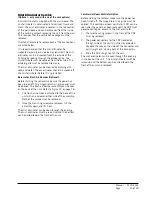
Condensate Drain ............................................... 14
Mist Eliminator Service ....................................... 15
Figures
Figure 1 Unit Dimensions .................................. 6
Figure 2 Removal of Unit From Skid ................... 7
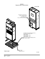
Figure 3 Proper Handling of Unit After Removal
from Skid ............................................ 8
Figure 4 Installation of Unit w/Wall Sleeve .......... 9
Figure 5 Shipping Assembly – Bracket Locations .. 10
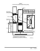
Figure 6 Installation of QC Wall Sleeve
Through a Window Opening ................. 11
Figure 7 Installation With Free Blow Plenum ..... 12
Figure 8 Ducted Application ............................ 12
Figure 9 Supply Duct Connections .................... 13
Figure 10 Filter Location ................................... 13
Figure 11A Side Drain (Side View) ........................ 14
Figure 11B Optional Rear Drain ............................ 14
Figure 11C Rear Drain (Top View) ......................... 14
Figure 12 Fresh Air Damper Removal .................. 16
Figure 13 Removal of Q-TEC ERV ....................... 17
Figure 14 Remove Locking Screws from Wheels ... 18
Figure 15 Unit Mounting Without Wall Sleeve ...... 19
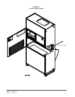
Figure 16 Component Location .......................... 20
Figure 17 Blower Motor Low Voltage Wire
Harness Plug ..................................... 22
Figure 18 Remote Thermostat Wiring "X" Option .. 23
Figure 19 Remote Thermostat Wiring "D" Option .. 24
Figure 20 Control Disassembly ........................... 27
Figure 21 Winding Test ...................................... 27
Figure 22 Drip Loop .......................................... 27
Figure 23 Internal 2-Way Valve Piping................. 28
Figure 24 Internal 3-Way Valve Piping................. 29
Tables
Table 1 Factory Built-In Electric Heat .................. 4
Table 2 Electrical Specifications ......................... 4
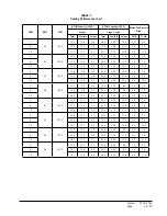
Table 3 Cooling Performance Chart .................... 21
Table 4 Operating Voltage Range ....................... 21
Table 5 Wall Thermostat ................................... 21
Table 6 Indoor Blower Performance ................... 25
Installation ............................................................. 18
Mounting the Unit .............................................. 18
Wiring – Main Power ........................................... 20
Wiring – Low Voltage ........................................... 21
General ............................................................. 21
Fluid Connections .............................................. 21
Low Voltage Connections ..................................... 22
Start Up ................................................................... 25
Optional CFM .................................................... 25
Important Installer Note ...................................... 25
Service Hints ..................................................... 25
Sequence of Operation ........................................ 25
Troubleshooting ECM
TM
Motors .......................... 26
Summary of Contents for QC Series
Page 6: ...Manual 2100 416L Page 6 of 29 FIGURE 1 Unit Dimensions...
Page 16: ...Manual 2100 416L Page 16 of 29 FIGURE 12 Fresh Air Damper Removal MOUNTING SCREW...
Page 23: ...Manual 2100 416L Page 23 of 29 FIGURE 18 Remote Thermostat Wiring Diagram X Option...
Page 24: ...Manual 2100 416L Page 24 of 29 FIGURE 19 Remote Thermostat Wiring Diagram D Thermostat Option...


