Manual 2100-670B
Page
22 of 33
Compressor
Compressor Components
Compressor
Three Phase Scroll Compressor Start Up Information
Scroll compressors, like several other types of
compressors, will only compress in one rotational
direction. Direction of rotation is not an issue with
single phase compressors since they will always start
and run in the proper direction.
However, three phase compressors will rotate in either
direction depending upon phasing of the power.
Since there is a 50-50 chance of connecting power
in such a way as to cause rotation in the reverse
direction, verification of proper rotation must be made.
Verification of proper rotation direction is made by
observing that suction pressure drops and discharge
pressure rises when the compressor is energized.
Reverse rotation also results in an elevated sound level
over that with correct rotation, as well as substantially
reduced current draw compared to tabulated values.
Verification of
proper rotation
must be made at the time
the equipment is put into service. If improper rotation
is corrected at this time, there will be no negative
impact on the durability of the compressor. However,
reverse operation for over 1 hour may have a negative
impact on the bearing due to oil pump out.
NOTE:
If compressor is allowed to run in reverse
rotation for an extended period of time, the
compressor’s internal protector will trip.
All three phase compressors are wired identically
internally. As a result, once the correct phasing is
determined for a specific system or installation,
connecting properly phased power leads to the same
Fusite terminal should maintain proper rotation
direction.
The direction of rotation of the compressor may be
changed by reversing any two line connections to the
unit.
Compressor Control Module (CCM)
The compressor control module is a low voltage
monitoring device necessary to monitor power and
indicate a low incoming voltage situation caused by
inadequate shore power or generator operation. The
monitoring device protects the unit against compressor
contactor “chatter” and reverse compressor rotation
during these situations.
Compressor protection device has an adjustable
30-second to 5-minute timer (red-dial). This module
features a delay-on-make for initial start up (or anytime
power is interrupted) for a minimum 2 minutes plus
10% of the red-dial setting. There is no delay during
routine operation of the unit. The compressor control
module also monitors the high pressure switch, and
will allow one automatic retry (after soft lockout delay)
before disabling the compressor in a hard lockout
(requires manual reset). If hard lockout does occur,
the ALR terminal on the CCM will become active with
24v, which will power the high pressure relay within
the wall unit. The relay contacts are monitored by the
unit controller. If the CCM indicates an alarm to the
wall unit controller, an alarm will be generated and the
compressor will be locked out by the controller.
NOTE:
The controller will remove cooling call on the Y
terminal of the CCM, reseting it almost instantly.
The compressor remains locked out by the
controller until manually cleared.
Switch is jumpered in this application. Instead, the low
pressure transducer is used for low pressure monitoring.
High Pressure Safety Switch
All units have a high pressure switch as a safety device.
This device will open when pressure in the system
reaches 650 PSIG. The sensor is directly connected to
the dedicated compressor control module. This module
will disable any call for cooling if the pressure is above
this limit. If tripped, the high pressure switch can be
reset by turning the output off and then back on again.
Refrigerant High Pressure Alarm
When the wall unit receives a signal from the
compressor control module (CCM) indicating a high
pressure event, the wall unit will generate an alarm.
Upon receiving the alarm, the wall unit will remove
the “Y” call from the CCM, resetting the status of the
CCM. The alarm will stay present on the wall unit until
manually cleared.
Alarm index numbers: 21, 40, 55, 70
In addition to the CCM, the discharge pressure
transducer is used to prevent a high pressure event.
When the discharge pressure is above the discharge
pressure alarm setpoint (set 30 pounds below high
pressure switch, which is 650), the system will disable
stage 2 of mechanical cooling.
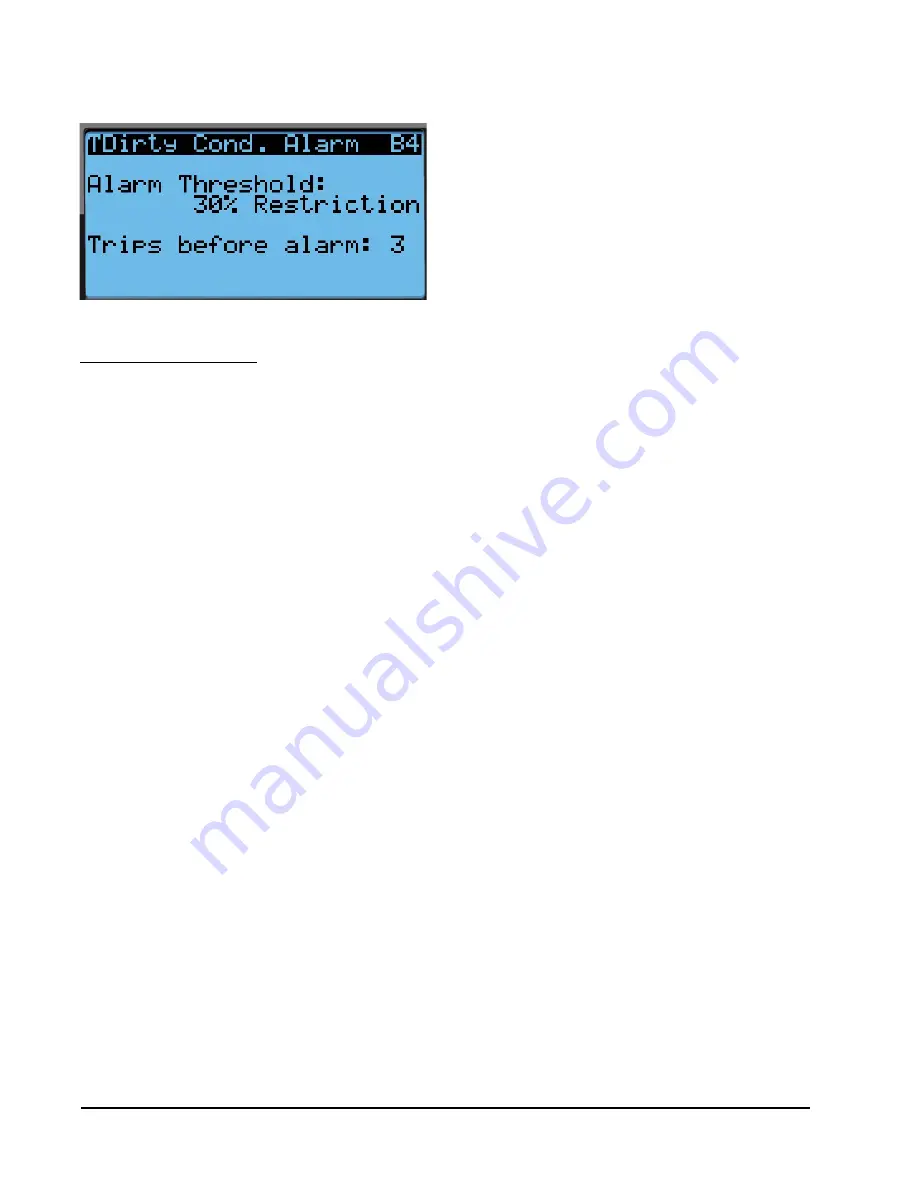
FIGURE 29
Adjusting Dirty Condensor Coil Alarm Settings


