Manual 2100-034G
Page
5 of 21
Unit Installation
–
Wall Mount
Unit Installation
Installation plays a key part in unit functionality, performance and safety. Product securing and placement, duct
design and supply/return location, electrical routing and condensate and defrost drainage all play key roles in making
sure a unit will perform per the design specifications.
WALL MOUNT Products – Mounting the Product on a Wall Surface
Outdoor products are normally mounted to an exterior wall surface, including brick,
cement block, metal or wood construction. These products are labeled as “WALL
MOUNT” units.
Before installation begins, the wall surface should be inspected by a
construction professional to ensure it will support the weight of the unit and accessory
items.
Approximate weights are available from the product specification sheet, and a
safety factor should be designed into the installation. Typical fasteners to attach the unit
to the wall using the integrated mounting flanges on both sides of the unit include tap
cons, bolts, studs and other fastening devices. The selection of the fasteners to be used
needs to be reviewed by a construction professional and decided upon based on the wall
construction and fastener strength required. It is important to follow all guidelines and
procedures covered in the installation instructions manual provided for the product.
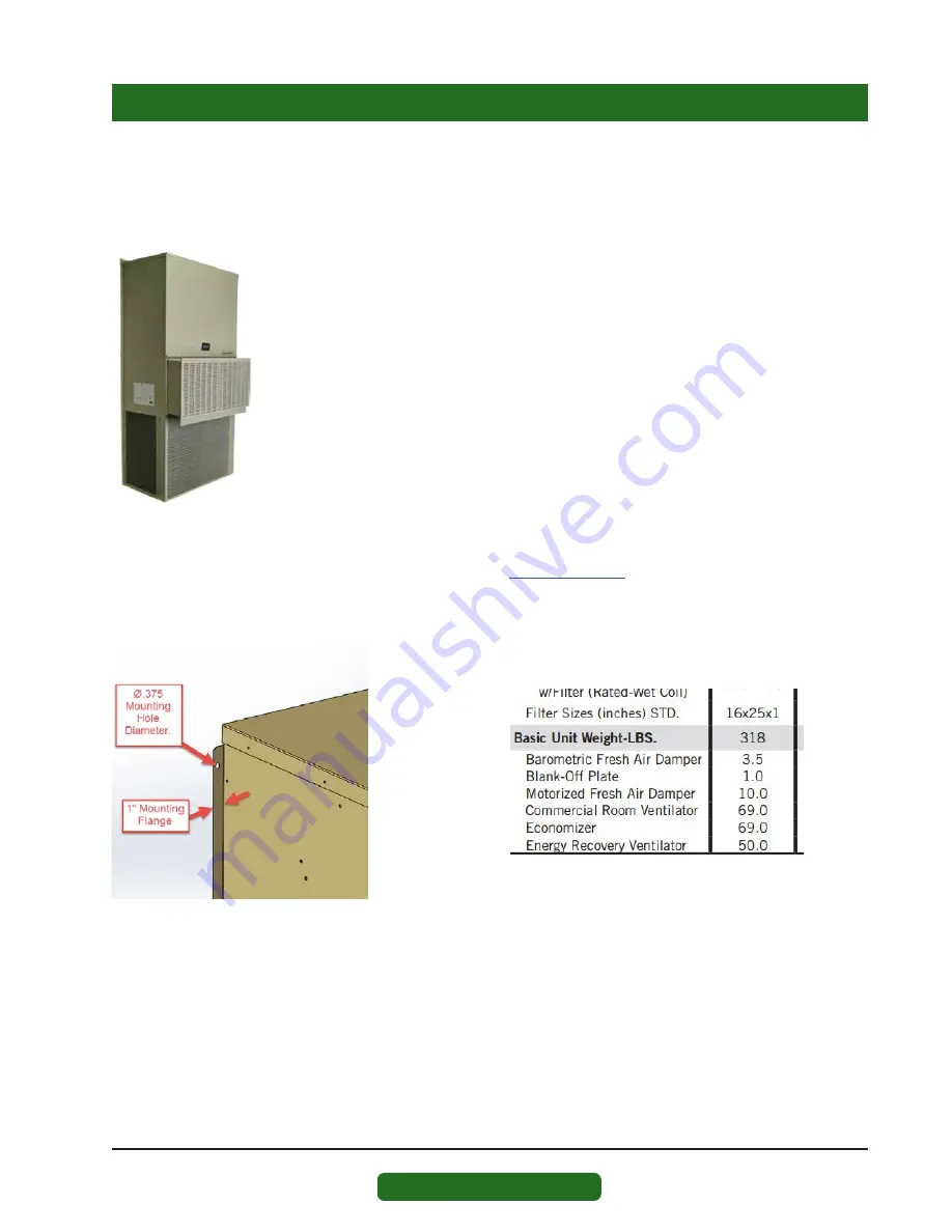
Built-In Mounting Flange Detail:
Outdoor WALL MOUNT products include a
mounting flange that is part of the cabinet
construction. Ø.375" holes are provided for
unit mounting unless specified otherwise in
installation instructions.
Specification Sheets:
Unit specification sheets provided at
www.bardhvac.com
include basic unit weights and
dimensions (see example below). Ventilation options and
other accessories must be added into the total weight of
the unit.
Specification Sheet Example
Summary of Contents for 11EER WA Series
Page 2: ......
Page 24: ......
Page 30: ...Manual 2100 479 Page 6 of 11 FIGURE 1 TYPICAL AIR CONDITIONING SYSTEM COOLING CYCLE MIS 369...
Page 31: ...Manual 2100 479 Page 7 of 11 FIGURE 2 TYPICAL HEAT PUMP SYSTEM COOLING CYCLE MIS 368...
Page 36: ......
Page 81: ......
Page 86: ...Manual 2110 1452G Page 5 of 17 This page intentionally left blank...
Page 90: ...Manual 2110 1452G Page 9 of 17 This page intentionally left blank...
Page 99: ......
Page 102: ......


