background image

R5914481 /02 XDX

54

1

2

Image 4–23 Bottom bracket

1

V3624376 screw M5 x 12

2

V3673791 washer D5,3 D15

7.

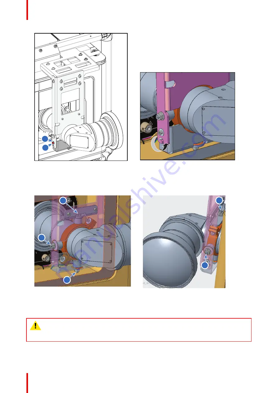
Adjust the 4 adjustment points to make sure the lens is correctly positioned. Use a flat screwdriver and
turn the positioning knobs against the lens.

2

1

4

4

3

Image 4–24

4.8 Suspending the projector from a truss

WARNING:

It is the responsibility of the installer to suspend the reinforcement frame in a safe and

secure fashion. Safety cables must be applied according to local regulations and standards. Safety
cables must be dimensioned for the applicable load and no drop distance is allowed or must be
limited as much as possible.

Installation procedures

Summary of Contents for XDX Series

Page 1: ...ENABLING BRIGHT OUTCOMES Installation manual XDX...

Page 2: ...Registered office Barco NV President Kennedypark 35 8500 Kortrijk Belgium www barco com en support www barco com Barco NV Beneluxpark 21 8500 Kortrijk Belgium www barco com en support www barco com...

Page 3: ...to deliver secure solutions and services to our customers while protecting Barco s intellectual property When product security concerns are received the product security incident response process will...

Page 4: ......

Page 5: ...5 3 3 Mount the projector in the reinforcement frame 27 3 4 Projector configurations 33 3 5 Initial inspection 36 3 6 Available lenses 37 3 7 Lens selection 39 4 Installation procedures 41 4 1 Accessi...

Page 6: ...ime 65 6 4 Switching the projector OFF 66 6 5 Software update 67 7 Projector covers 71 7 1 Removal of the front cover 72 7 2 Removal of the rear cover 72 7 3 Removal of the mains side cover 73 7 4 Mou...

Page 7: ...nderstand and follow all safety guidelines safety instructions and warnings mentioned in this chapter before installing and using the XDX projector After this chapter additional warnings and cautions...

Page 8: ...nergy of the light source which is equivalent with lamp based systems Thermal retinal eye injury is possible when exposed within the Hazard Distance HD The HD is defined from the projection lens surfa...

Page 9: ...a suitable UPS unit The building has to be provided with a circuit breaker of max 16A to protect the UPS The building installation has to be provided with a circuit breaker of max 40A to protect the...

Page 10: ...ojection lens surface towards the position of the projected beam where the irradiance equals the maximum permissible exposure as described in the chapter High Brightness precautions Hazard Distance pa...

Page 11: ...his could result in disrupting the air flow inside the projector causing overheating Overheating may lead to the projector shutting down during operation The projector must always be installed in a ma...

Page 12: ...placement parts which have the same characteristics as the Barco original part Unauthorized substitutions may result in degraded performance and reliability fire electric shock or other hazards Unauth...

Page 13: ...EAM IS PERMITTED RG3 IEC EN 62471 5 2015 CLASS 1 IEC EN 60825 1 2014 HAZARD DISTANCE CONSULT SAFETY MANUAL RG3 IEC EN 62471 5 2015 CLASS 1 IEC EN 60825 1 2014 RG3 IEC EN 62471 5 2015 CLASS 1 IEC EN 60...

Page 14: ...STALLATION AVANT DE RACCORDER AU R SEAU UPS UPS Screened on Mains cover CAUTION DOUBLE POLE NEUTRAL FUSING HIGH RESIDUAL VOLTAGE WARNING RISK OF ELECTRIC SHOCK SWITCH OFF AND UNPLUG BEFORE REMOVING TH...

Page 15: ...emit light into an uncontrolled area where persons may be present should be positioned in accordance with the fixed projector installation parameters resulting in a HD that does not extend into the a...

Page 16: ...l only be transferred to laser light show variance holders This is applicable for dealers and distributors since they may need to install the LIP demo install and or they transfer sell rent lease the...

Page 17: ...ed while observing the diffuse surface of the rear projection screen As described in High Brightness precautions Hazard Distance page 14 it is mandatory to create a restricted zone within the beam are...

Page 18: ...2 0 2 5 3 0 3 5 4 0 4 5 5 0 5 5 6 0 6 5 7 0 7 5 8 0 8 5 9 0 9 5 10 0 10 5 11 0 11 5 12 0 Hazard Distance m Throw Ra o XDX 4K40 Image 1 4 1 7 Compliance UK Compliance UK This product is fit for use in...

Page 19: ...19 R5914481 02 XDX 2 1 Conventions 20 2 2 Air flow 20 2 3 Web Communicator 21 System overview 2...

Page 20: ...t side of the projector User input side B Back side of the projector 2 2 Air flow Air flow projector The XDX projector has two air outlets and three air inlets The air inlets are located on the front...

Page 21: ...n provides all the necessary tools necessary to setup and control the connected projector A comprehensive array of easy to access menu pages provide the projectors digital input output and screen disp...

Page 22: ...r calibration and configuration with an existing automation system All actions can be activated by a simple click Depending on the user level functions are enabled or disabled in the application The e...

Page 23: ...as minimum and maximum allowed ambient temperature humidity conditions required safety area around the installed projector required power net etc Furthermore careful consideration of things such as im...

Page 24: ...2 ft This in accordance with the following table Altitude m Altitude ft Temp C Temp F 0 0 40 104 2 000 6 562 40 104 2 500 8 202 39 102 3 000 9 842 38 100 3 500 11 483 37 99 4 000 13 123 35 97 Main Pow...

Page 25: ...light source The connection between the UPS unit and the UPS inlet of the projector must be done with a certified AC power supply cord of minimum 1 50 mm or 14 AWG and minimum 300 V The XDX does not h...

Page 26: ...the box 3 Remove the top plate 4 Remove the safety manuals 5 Remove any foam piece present between the cardboard box and the projector Image 3 2 Removing foam manuals and other optional cardboard 6 Re...

Page 27: ...epack your projector as it was originally packed at the factory The projector is delivered with a plastic cover inside the Lens Holder This to prevent intrusion of dust and foreign particles The proje...

Page 28: ...asher V3673791 16 x washer V3673826 16 x bolt G186470 16 x nut B364326 4 x B362161 4 x B361787 Required tools Allen wrench 3 mm Allen wrench 4 mm Allen wrench 6 mm Allen wrench 8 mm Torx screwdriver T...

Page 29: ...e projector and turn out the 4 feet These feet will be reused to mount the projector in its frame Use an adjustable wrench to loosen these feet 4 While the projector is lift up slide the frame under t...

Page 30: ...e on both vertical profiles a small bracket as indicated Fixate each bracket with 2 Torx screw V3624376 Image 3 9 7 Place the front R8798068 and back reinforcement bar R8796564 on the top plate of the...

Page 31: ...ame Caution Use high strength threadlocker on the rigging screws thread Tighten the rigging screws with a torque of 40 Nm 40Nm Image 3 11 2 Install the 4 pins on the top of the frame Note These pins c...

Page 32: ...wrench Caution Use sufficient high strength threadlocker on the set screws Image 3 14 5 Mount the vertical fence fixation plates as illustrated Place the fixation plate on its place and insert 2 bolt...

Page 33: ...or can be installed on a table or be hung from a truss beam and this in a front projection or rear projection configuration This can happen as long as the projector is not hung upside down the top cov...

Page 34: ...a SC Screen Rear projection The projector is installed either in on a table or hanging from a truss beam at the other side of the screen opposite to the audience SC TH BA Image 3 18 Examples of Rear p...

Page 35: ...the projector can be positioned in On Axis or Off Axis configuration On Axis configuration means that the projector is positioned so as to have the centre of the lens coinciding with the centre of the...

Page 36: ...tions of projector tilt and projector rotation can be used as a general rule of thumb make sure the top cover does not point downward 3 5 Initial inspection General Before shipment the projector was i...

Page 37: ...ld be notified as soon as possible if this is not the case 3 6 Available lenses This list only takes into account active lenses at the moment of release of this manual Lenses that have become end of l...

Page 38: ...h Brightness 1 46 2 10 1 R98565272 XLD lens High Contrast 1 46 2 10 1 R9856529 XLD lens High Brightness 2 00 3 35 1 R98565292 XLD lens High Contrast 2 00 3 35 1 R9855947 XLD lens High Brightness 2 53...

Page 39: ...te https lenscalculator barco com to determine the possible lenses for your configuration The Lens Calculator window opens Image 3 22 Lens calculator The Lens Calculator can also be used to determine...

Page 40: ...R5914481 02 XDX 40 Installation preparations...

Page 41: ...ctor 42 4 3 Connecting the projector with the power net 44 4 4 Connecting a UPS with the projector electronics 45 4 5 Installation of a lens 47 4 6 Removal of a lens from the lens holder 49 4 7 Instal...

Page 42: ...the power input The power input of the projector can be configured in one of three different configurations depending on the local power supply In a Y configuration 3W N PE for a three phase power su...

Page 43: ...the mono configuration pins U1 U2 V1 V2 W1 and W2 Use a 10 mm nut driver Image 4 3 2 Take off the four mounted links A B C and D 3 Mount the links as illustrated depending on the configuration 1 Y con...

Page 44: ...itch circuit breakers and ground fault current interrupters The installation shall be done according to the local electrical installation codes CAUTION ALL POWER CONNECTIONS to the XDX projector are m...

Page 45: ...each wire Tip In case of mono phase wiring which only has L N and PE The L wire should be connected to the rightmost of the three phase terminals reference 5 However ensure that you correctly connect...

Page 46: ...more info see Accessing the power connections page 42 2 Loosen the top nuts on the six UPS configuration pins Use a 10 mm nut driver Image 4 8 3 Replace the links as illustrated Image 4 9 4 Guide the...

Page 47: ...d seal it Tighten the two screws reference 1 using a T20 Torx screwdriver 4 5 Installation of a lens How to install a lens into the B lens holder while using the optical adapter 1 Place the lens holde...

Page 48: ...ert the lens in such a way that the lens connector matches the socket reference 2 Image 4 13 Lens installation 5 Insert the lens until the connector seats into the socket Warning Do not release the le...

Page 49: ...holder 4 6 Removal of a lens from the lens holder How to remove 1 Support the lens with one hand while you unlock the lens holder by sliding the lock handle outwards and then towards the unlocked posi...

Page 50: ...l projector packaging back into the lens opening to prevent intrusion of dust Image 4 17 4 7 Installation of UST lens support Required tools Allen wrench 5 mm Allen wrench 4 mm Flat screwdriver How to...

Page 51: ...Mount hoop 1 G1161140 screw M6 x 25 2 V3624376 washer D 6 4 D18 3 R3661581 nut M6 Image 4 19 Mount under 45 3 Install the top fixation bracket R8798044 on top bar of the XDX projector with 2 screws an...

Page 52: ...stalled top bracket using 4 screws and 4 washers 1 2 Image 4 21 Second top bracket 1 V3624376 screw M5 x 12 2 V3673791 washer D5 3 D15 5 Fixate the front bracket on the second top bracket using 5 iden...

Page 53: ...in position The main purpose is to make sure the 4 adjustment points on the bracket are symmetrical to the lens 1 2 Image 4 22 Mount front bracket 1 V3624376 screw M5 x 12 2 V3673791 washer D5 3 D15 6...

Page 54: ...knobs against the lens 2 1 4 4 3 Image 4 24 4 8 Suspending the projector from a truss WARNING It is the responsibility of the installer to suspend the reinforcement frame in a safe and secure fashion...

Page 55: ...ouble clamps Take into account the total weight of projector and frame suspended from the truss For the XDX the working load limit for each clamp must be bigger than 269 kg 593 lbs The clamps can only...

Page 56: ...Secure the reinforcement frame and truss installation using safety cables Warning Make sure the safety cables are mounted on the longest bars on the side of the frame that faces the truss beam the sa...

Page 57: ...tion 58 5 2 controller of the projector 58 5 3 ICP D 59 About this chapter This chapter describes the functionality of the touch display as well as the different input and communication ports of your...

Page 58: ...port 2 Use for projector control and automation E g Touch display content server not for content streaming As there is a need to daisy chain projectors when they are on an Ethernet network an Ethernet...

Page 59: ...ional when the projector is in Standby mode So if the factory predefined macro to wake up the projector is assigned to one of the free GPI port numbers the projector can be awakened via GPI The GPI po...

Page 60: ...nking Orange Operating System start up Blinking Green Orange Security Manager Image Integrity tests Blinking Green Blinking Yellow Security Manager Self Test Green Blinking Green Starting Applications...

Page 61: ...witching the projector OFF 66 6 5 Software update 67 About this chapter This chapter contains the Switch ON and Switch OFF procedures for the XDX projector These procedures highlight all important poi...

Page 62: ...nd active touch display is on if available Web Communicator is active and light is ON Full GREEN Going to ECO mode Turning electronics and light source OFF Blinking green 2 3 4 5 6 1 Image 6 1 1 Mains...

Page 63: ...e Power button and GPI 1 4 input on the Cinema Controller Power state diagram ON ON 1 sec 6sec Image on the screen START UP FORCE SHUTDOWN SHUTDOWN ECO ECO READY READY OFF OFF Image 6 3 Power State di...

Page 64: ...power 3 Ensure that the correct lens is installed for your application 4 Press the power button to switch the projector ON The projector will start up and the touch display will start its initializati...

Page 65: ...ss of 1 second The Light source will start warming up 8 Press the Dowser button to open the dowser How to switch on remotely using only GPI3 1 Ensure that the XDX projector is installed onto a stable...

Page 66: ...4 admin Admin1234 Service technician st Service1234 Show manager show Show1234 show Show1234 Projectionist proj Proj1234 For security reasons it is advised to change these passwords as soon as possibl...

Page 67: ...s The projector will go to OFF mode or Send a signal via GPI3 for more than six second The projector will go to OFF mode 6 5 Software update How to update the software 1 Download the latest firmware f...

Page 68: ...the Barco website Click on myBarco and login to get access to secured information Registration is necessary If you are not yet registered click on New to myBarco and follow the instructions With the c...

Page 69: ...gress 2 Once the software package has been installed the following message will be prompted and the projector will reboot Image 6 13 Example of the prompted reboot message 3 Take note While rebooting...

Page 70: ...R5914481 02 XDX 70 Starting the projector for the first time...

Page 71: ...ther in this chapter The maintenance and servicing procedures also refer to this chapter if required The procedures in this chapter describe with detailed step by step actions and illustrations how to...

Page 72: ...erence 1 1 Image 7 1 2 Rotate and move the bracket to a position it won t hinder you while removing the front cover 3 Slide the front cover to the side of the Input Communication Unit towards the fram...

Page 73: ...ion it won t hinder you while removing the rear cover 3 Slide the rear cover towards the bar of the frame reference 2 as much as possible Note The handles do not click open They are fixed into the cov...

Page 74: ...he side cover and take it out of the frame Image 7 5 7 4 Mounting the mains side cover Required tools Torx screwdriver T20 How to mount 1 Make sure the light source side cover is mounted 2 Place and s...

Page 75: ...e the topside of the cover near the cover hooks on the top of the rear frame reference 2 3 Slide the clips in the rear cover over the cover hooks 1 2 Image 7 7 Sliding in the rear cover 4 Move the loc...

Page 76: ...ttom of the projector frame reference 1 2 Slide the clips in the front cover over the smaller cover hooks in the top of the frame reference 2 1 2 3 4 Image 7 10 Sliding in the front cover 3 Move the l...

Page 77: ...77 R5914481 02 XDX 5 Image 7 11 Locking the safety bracket Projector covers...

Page 78: ...R5914481 02 XDX 78 Projector covers...

Page 79: ...79 R5914481 02 XDX A 1 Dimensions of the projector 80 Dimensions A...

Page 80: ...CENTER OFGRAVITY AIR INLET AIR INLET CENTER OF GRAVITY 760 699 1315 4 1470 288 573 78 535 859 675 MAX 499 44 4X 613 221 44 330 97 760 42 5 804 366 273 481 83 137 MAX 295 Image A 1 All dimension given...

Page 81: ...81 R5914481 02 XDX Dimensions of the projector in the frame OY 1025 1470 773 Image A 3 All dimension given in mm Dimensions...

Page 82: ...R5914481 02 XDX 82 Dimensions...

Page 83: ...jection lens at which the intensity or the energy per surface unit becomes lower than the applicable exposure limit on the cornea or on the skin The light beam is considered to be unsafe for exposure...

Page 84: ...R5914481 02 XDX 84 Glossary...

Page 85: ...h Allen wrench 3 mm Allen wrench 4 mm Allen wrench 5 mm Allen wrench 6 mm Allen wrench 8 mm Flat screwdriver Hoisting tool Knife Nut driver 10 mm Open end wrench 24 mm Open end wrench 36 mm Side cutte...

Page 86: ...R5914481 02 XDX 86 List of tools...

Page 87: ...configuration 42 Dimensions 79 Projector 80 E Enclosed projection 16 F Front cover Mounting 76 Removal 72 G General considerations 8 GPI port 59 GPO port 59 H Hazard Distance 14 16 Modifying optics 18...

Page 88: ...tor configurations 33 Projector covers Installation 71 Removal 71 R Rear cover Mounting 75 Remove 72 Rear projection 16 Reinforcement frame Mount 27 Removal Front cover 72 Projector covers 71 Rotation...

Page 89: ......

Page 90: ...www barco com R5914481 02 2022 03 16...

Reviews: